Design and simulate parts and assemblies
Sketch, model parts, build assemblies and make engineering drawings, on your desktop or in the browser.


Parametric modeling
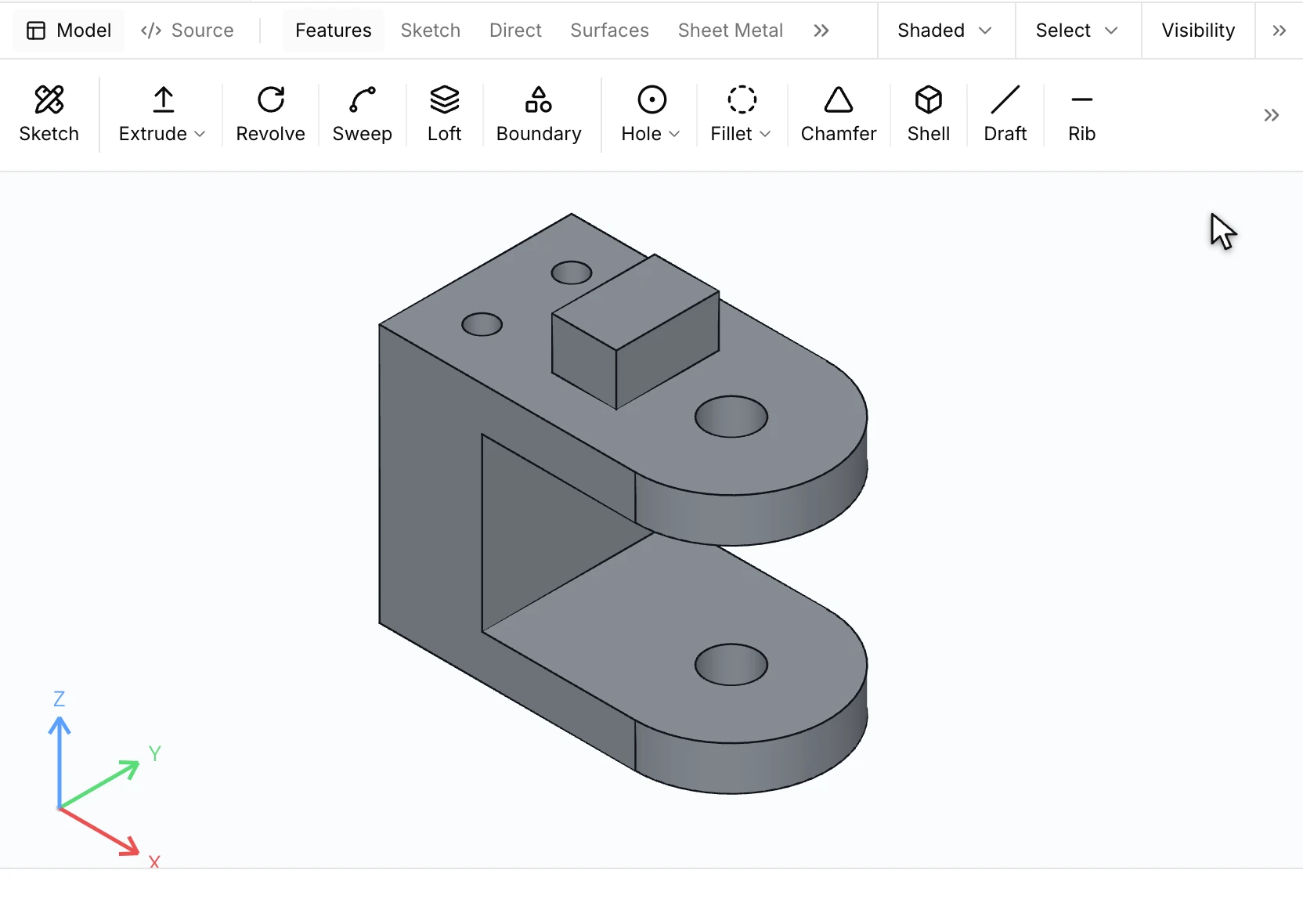
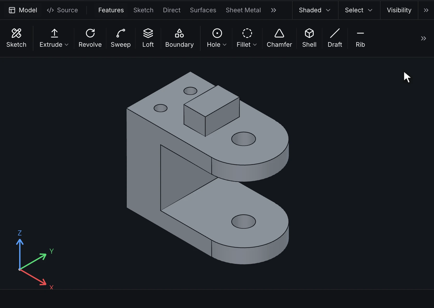
RunMat has the modeling tools a modern part needs: sketch a profile, turn it into a solid, then add surfaces, sheet metal, weldments and mold tools, and check the result. Change an input, such as a width of 80 mm, and the features replay to rebuild the part.
Sketch profiles to build on
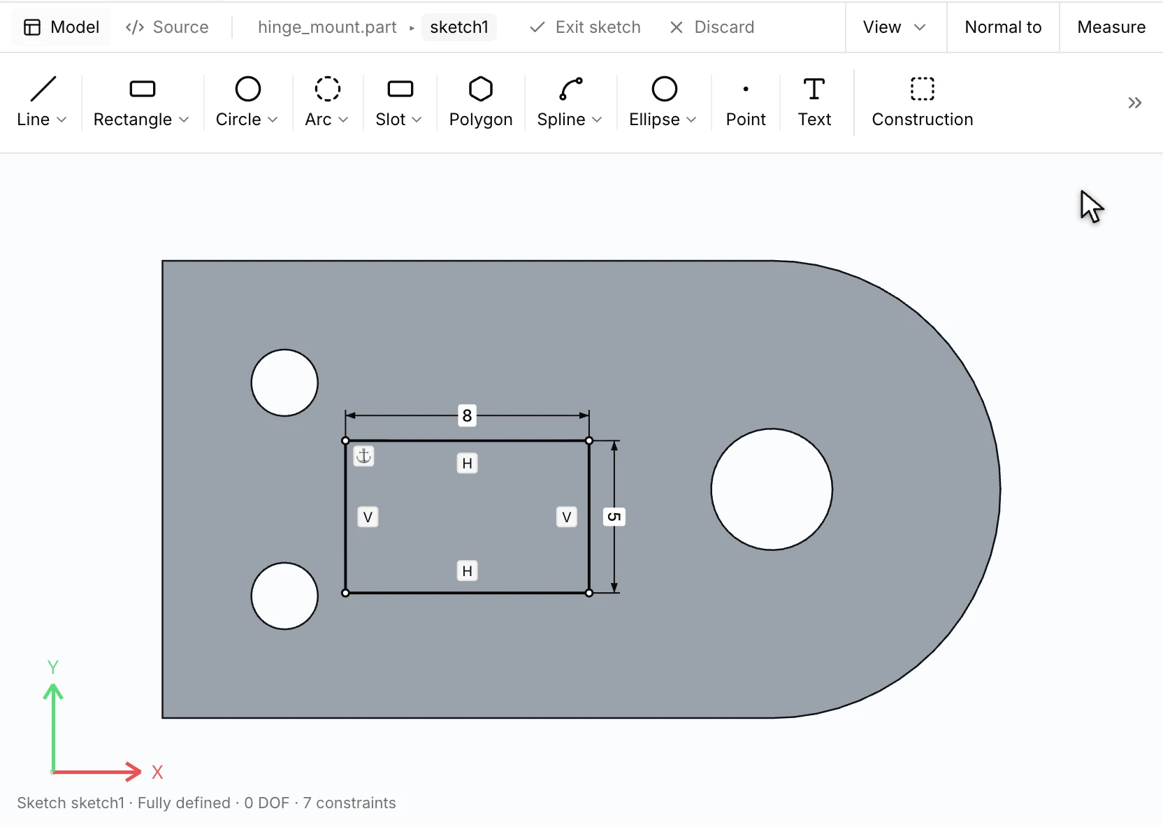
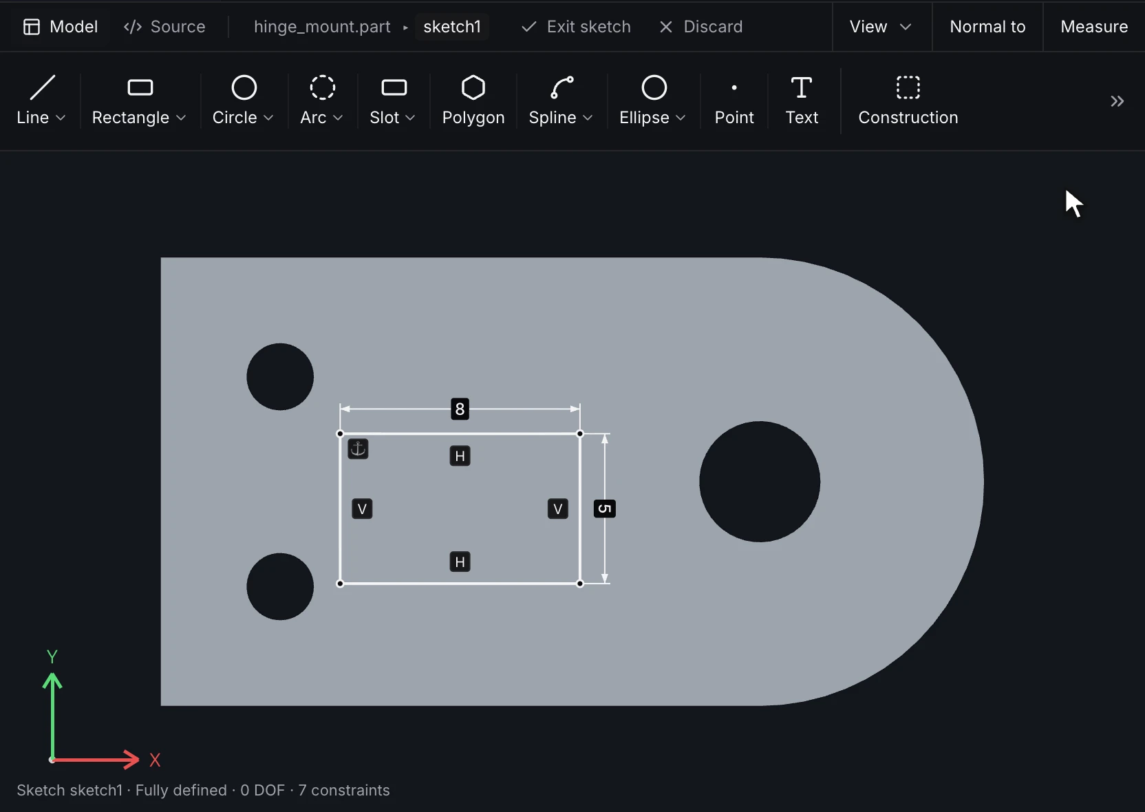
Draw constrained 2D profiles on a plane or a face. The sketch shows how many degrees of freedom are left, so you can see when it's ready to build on.
- Line, rectangle, circle, arc, slot, polygon, spline, ellipse, point and text
- Dimensions, plus parallel, perpendicular, tangent, coincident, equal and fix constraints
- Trim, extend, offset, split and stretch
- Sketch fillet and chamfer, and construction geometry
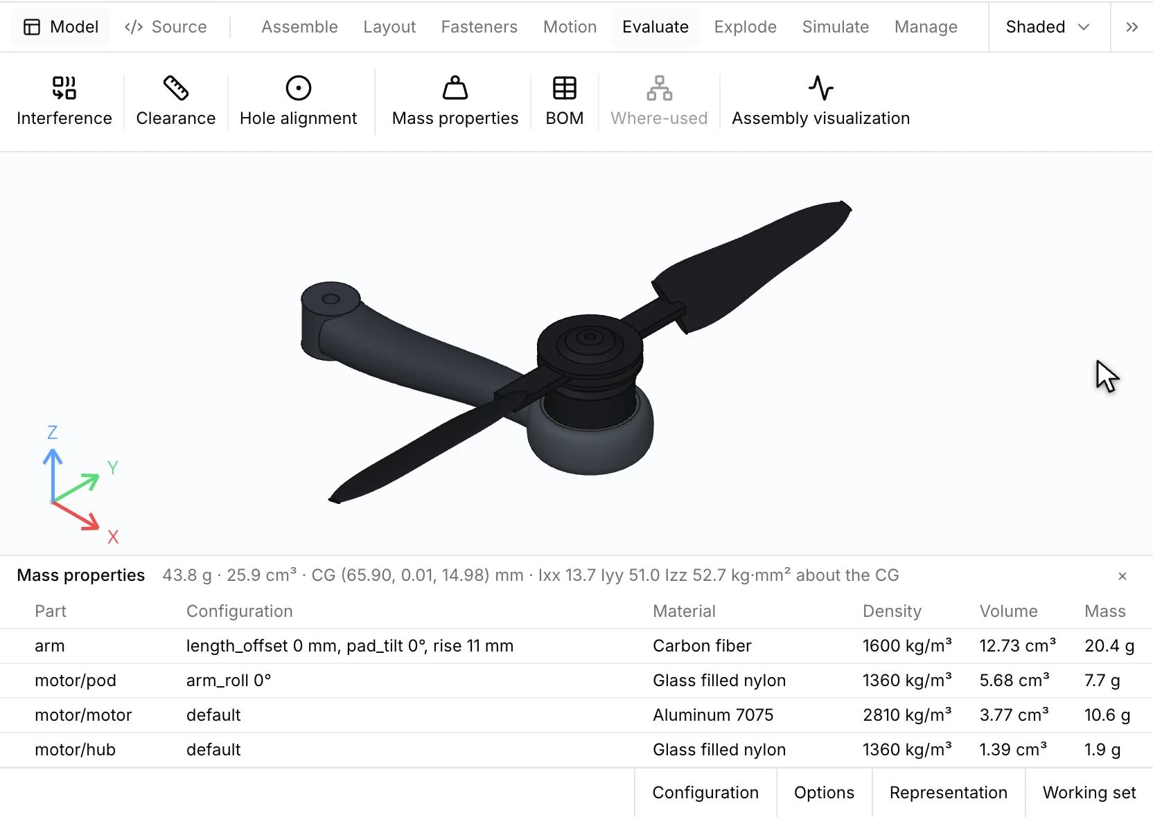
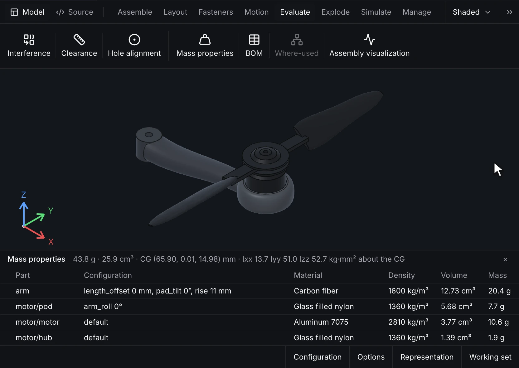
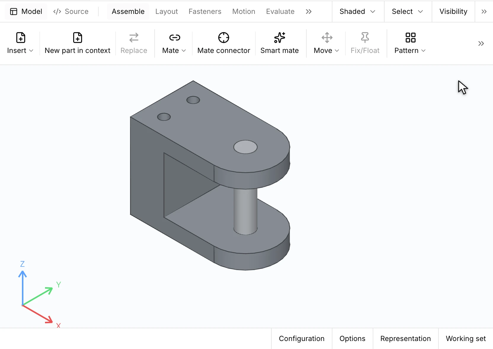
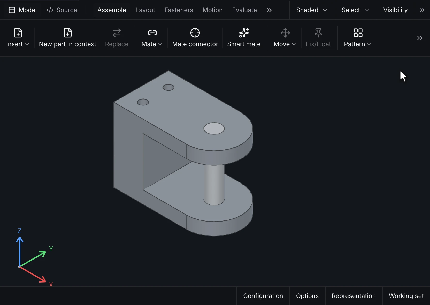
Assemblies, mates and a bill of materials
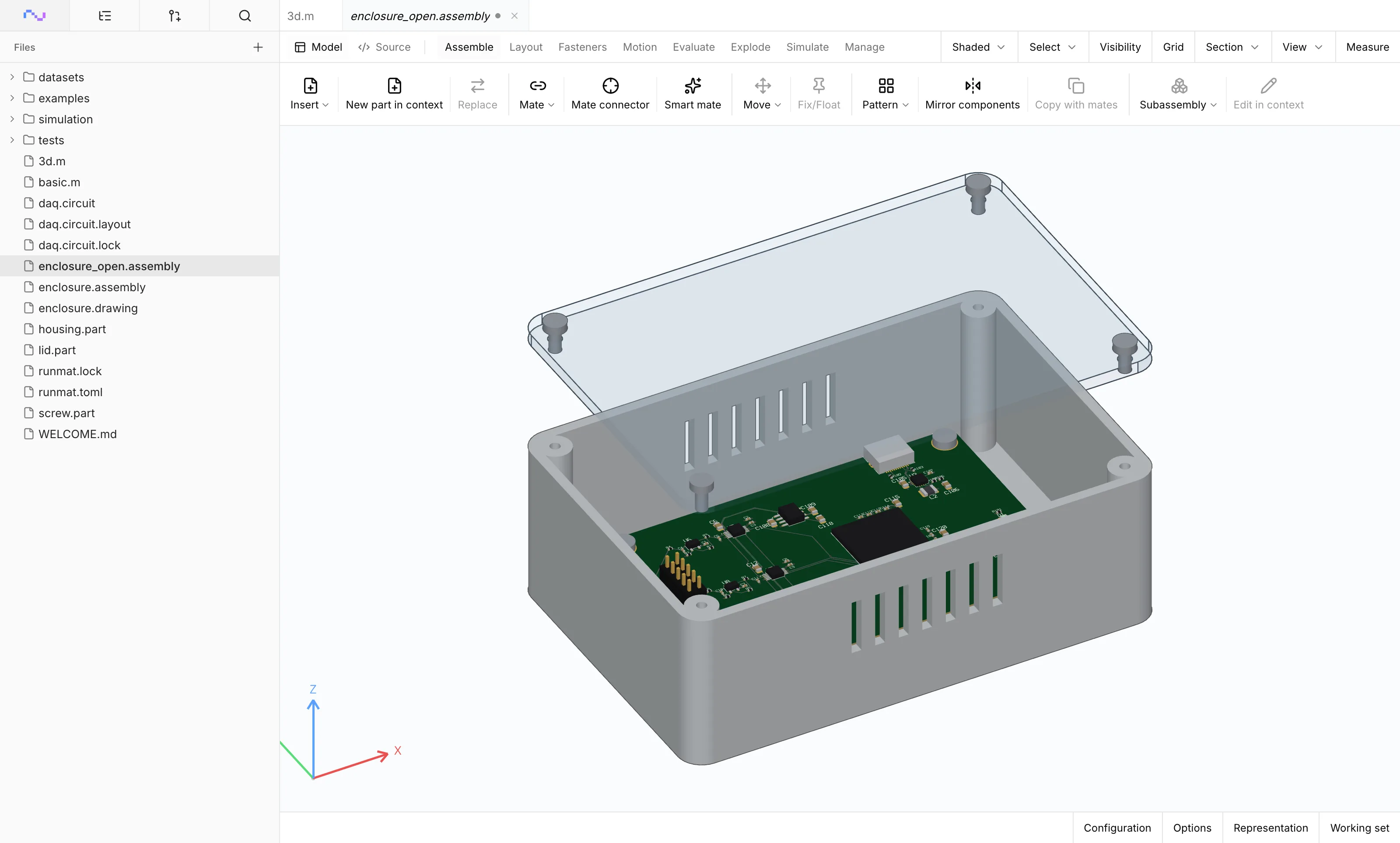
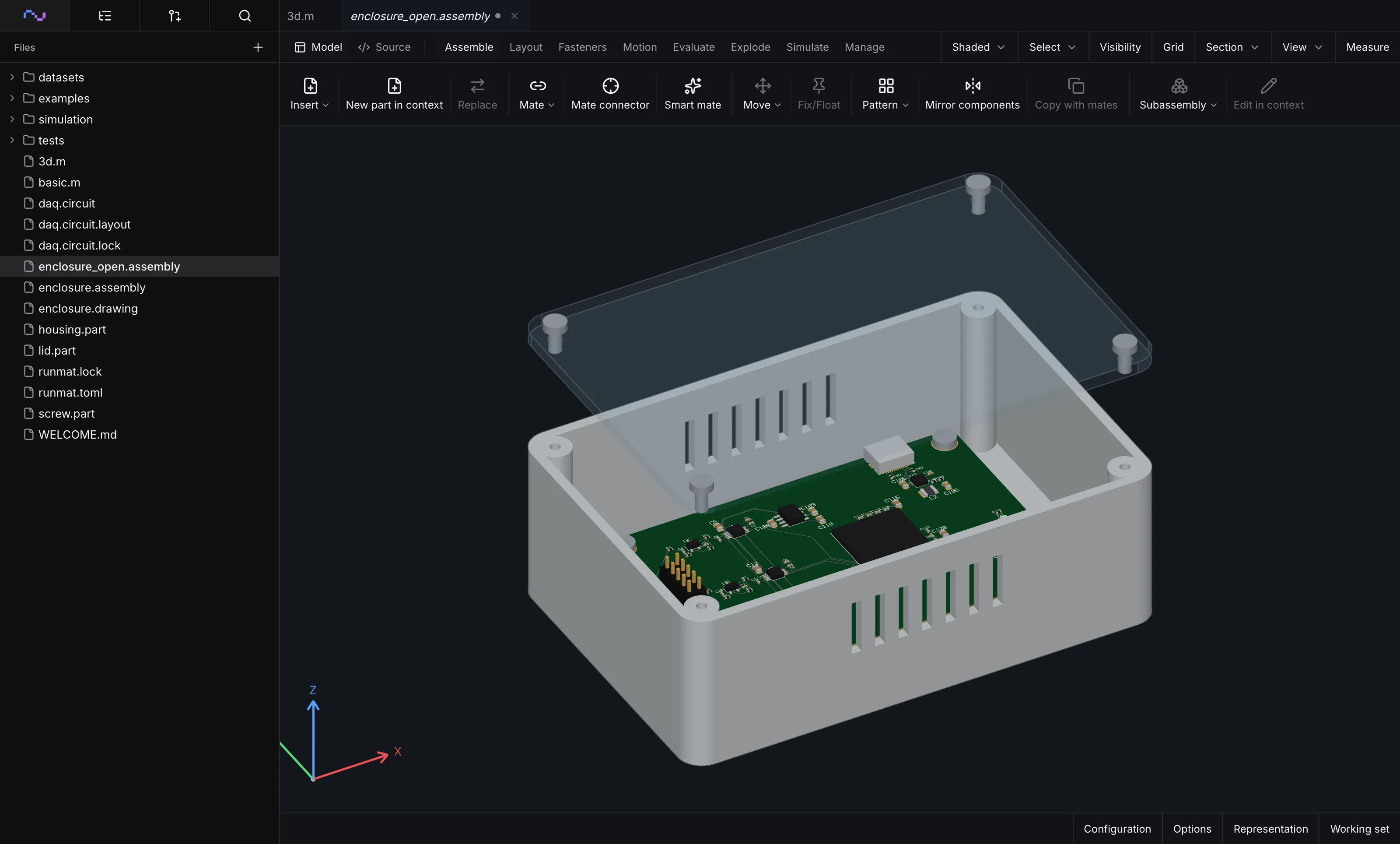
Insert parts, boards and subassemblies and mate them on named faces, edges and points: fasten, revolute, slider, cylindrical, planar, ball, pin-slot and path along picked edges, plus gear, rack-and-pinion, screw and cam relations, with offsets and limits. Place mate connectors with offsets where a part has no face to mate to. See the degrees of freedom left at a glance.
Export a bill of materials with part numbers, materials and masses. Check interference and clearance against a stated minimum, save exploded views and named positions, and lay out a product top-down from a skeleton part.
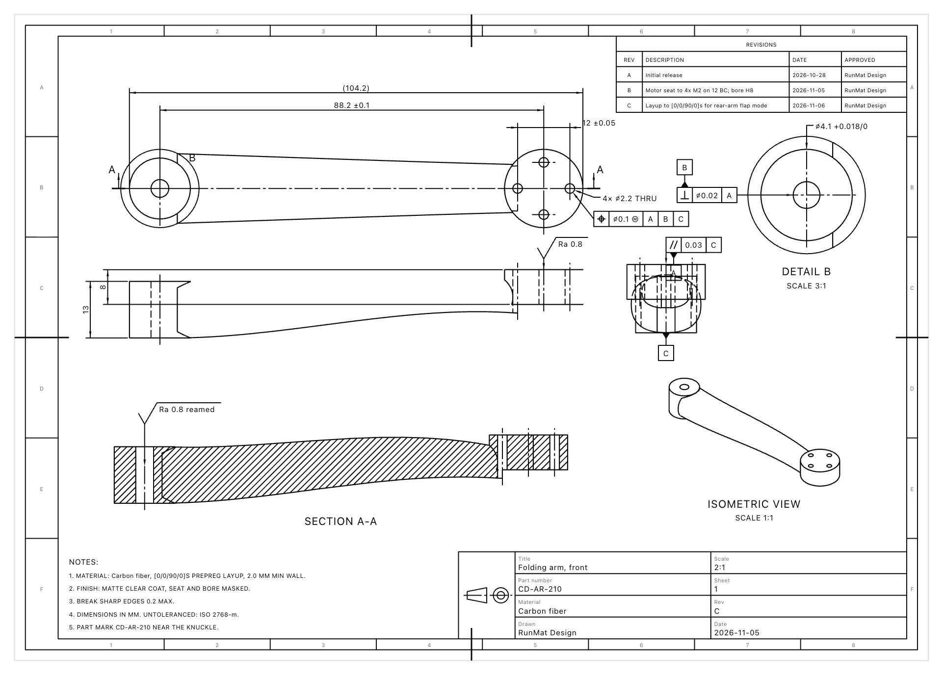
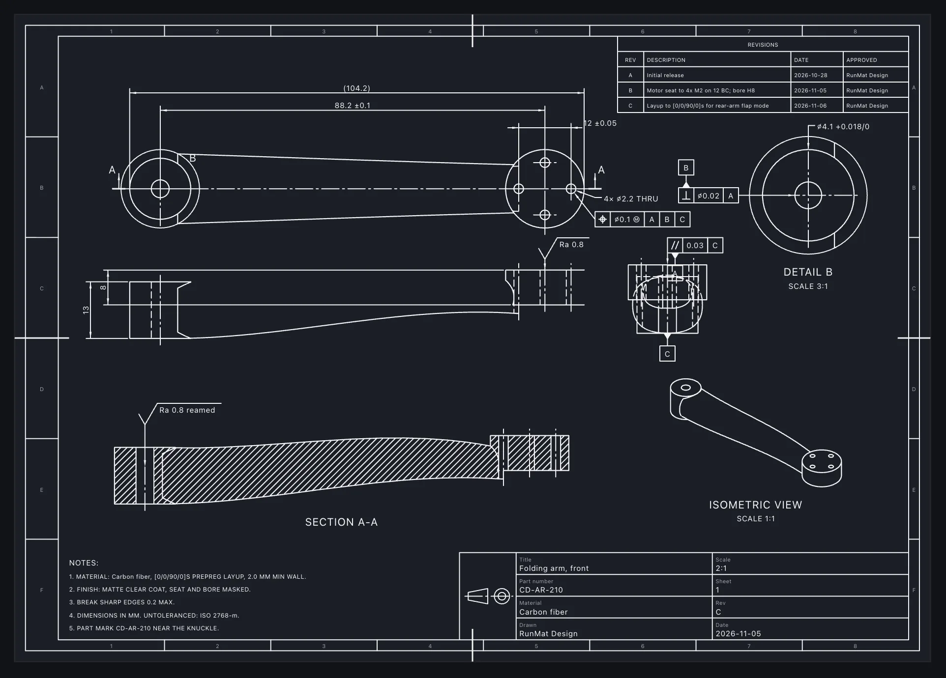
Engineering drawings that update with the model
Place standard, projected, section and detail views, then add dimensions, hole callouts and GD&T to ISO or ASME. Dimensions follow the model, so they update when the part changes.
Fill title blocks from part properties, add general notes, balloon assembly drawings from the parts list, and start a sheet with auto-drawing on a standard or custom sheet size. Export to PDF, SVG, DXF and DWG at true scale.
Simulate your parts before you build them
Find out whether a part holds its load, overheats or resonates while it's still a model, so the problems show up on screen instead of in a prototype, a tooling change or a field return.
Assign materials, loads, supports and boundary conditions to named faces, shown as symbols on the model, then run static stress, modes, buckling and contact, steady and transient heat, thermal stress and acoustics on parts and assemblies. Check each result against a limit you set, such as a stress allowable or a temperature, and after a design change the study reruns on the new geometry with its setup in place.
3D CAD capabilities
Sketch
- Lines, arcs, circles, slots, splines, ellipses and text
- Dimensional and geometric constraints, with degrees of freedom shown
- Trim, extend, offset, sketch fillet and chamfer
- Construction geometry and reference planes
Features
- Extrude, revolve, sweep, loft and boundary, from a sketch region or a face
- Holes from standard hole series, fillet, chamfer, shell, draft and rib
- Linear and circular patterns, mirror, booleans and split
- Multi-body parts, equations and configurations
Sheet metal and more
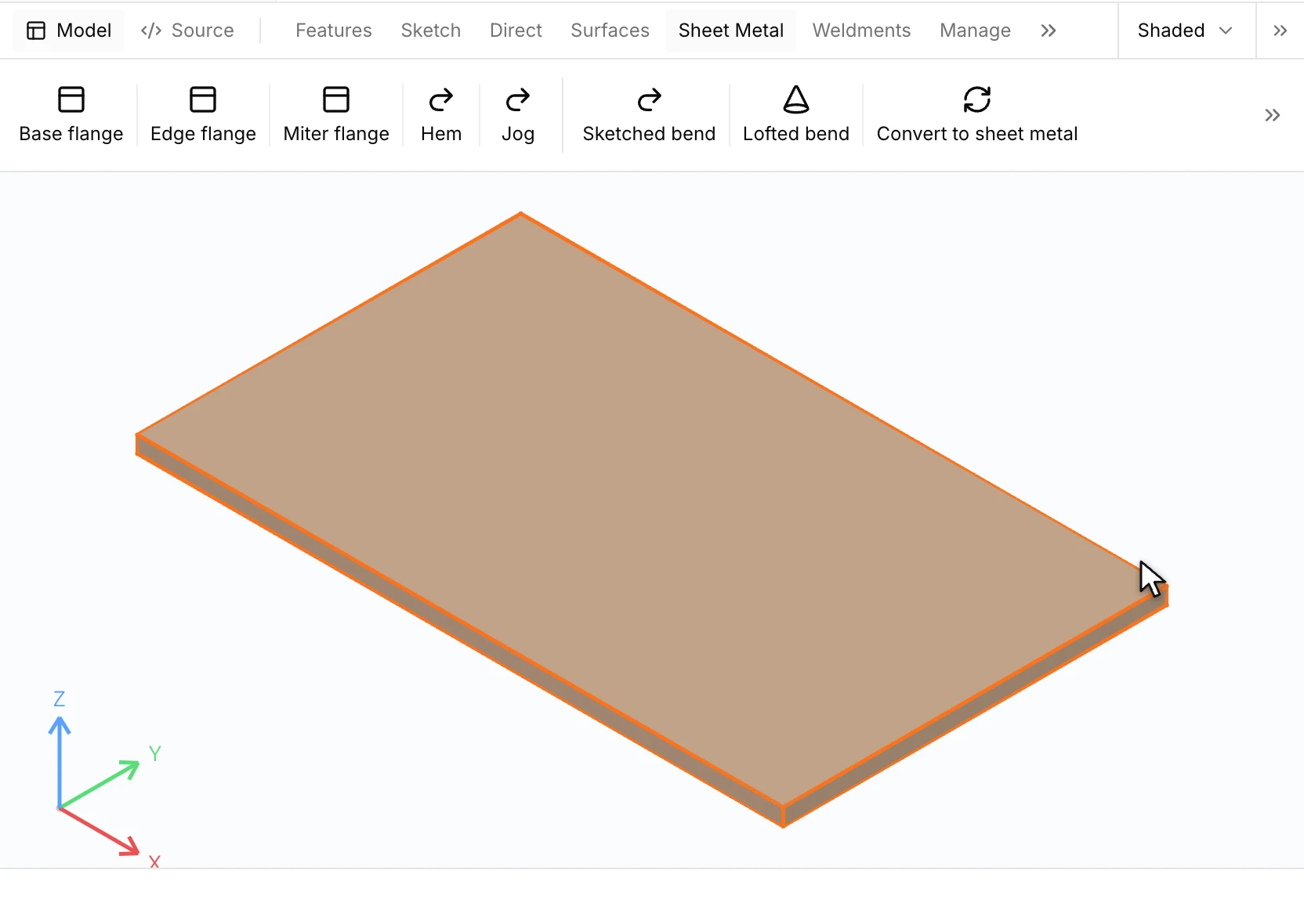
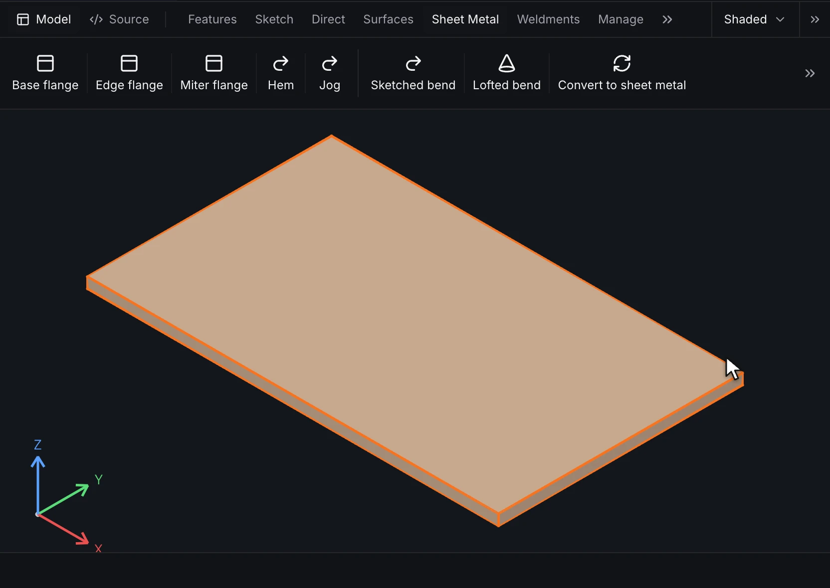
- Flanges, miter flanges, bends and a flat pattern, or a solid converted to sheet metal
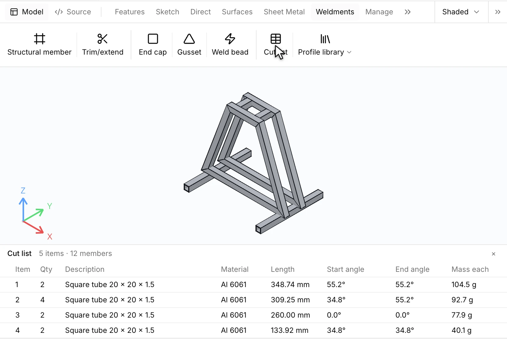
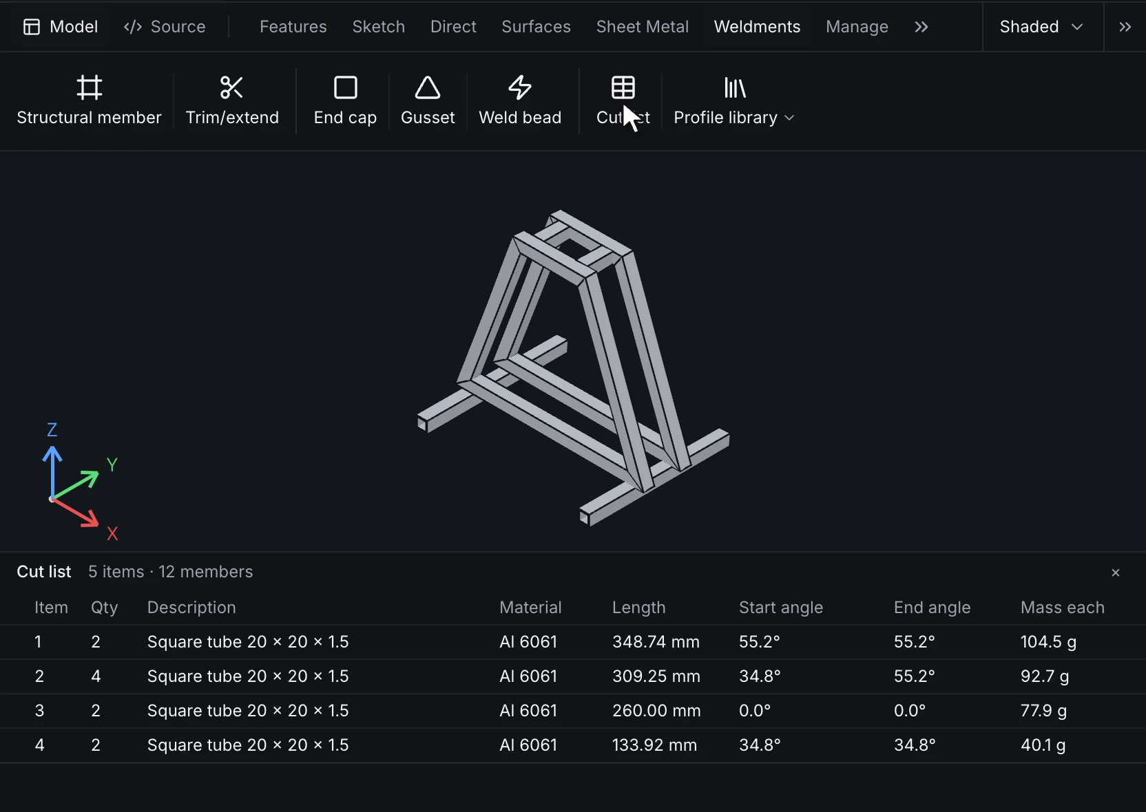
- Weldments with a cut list
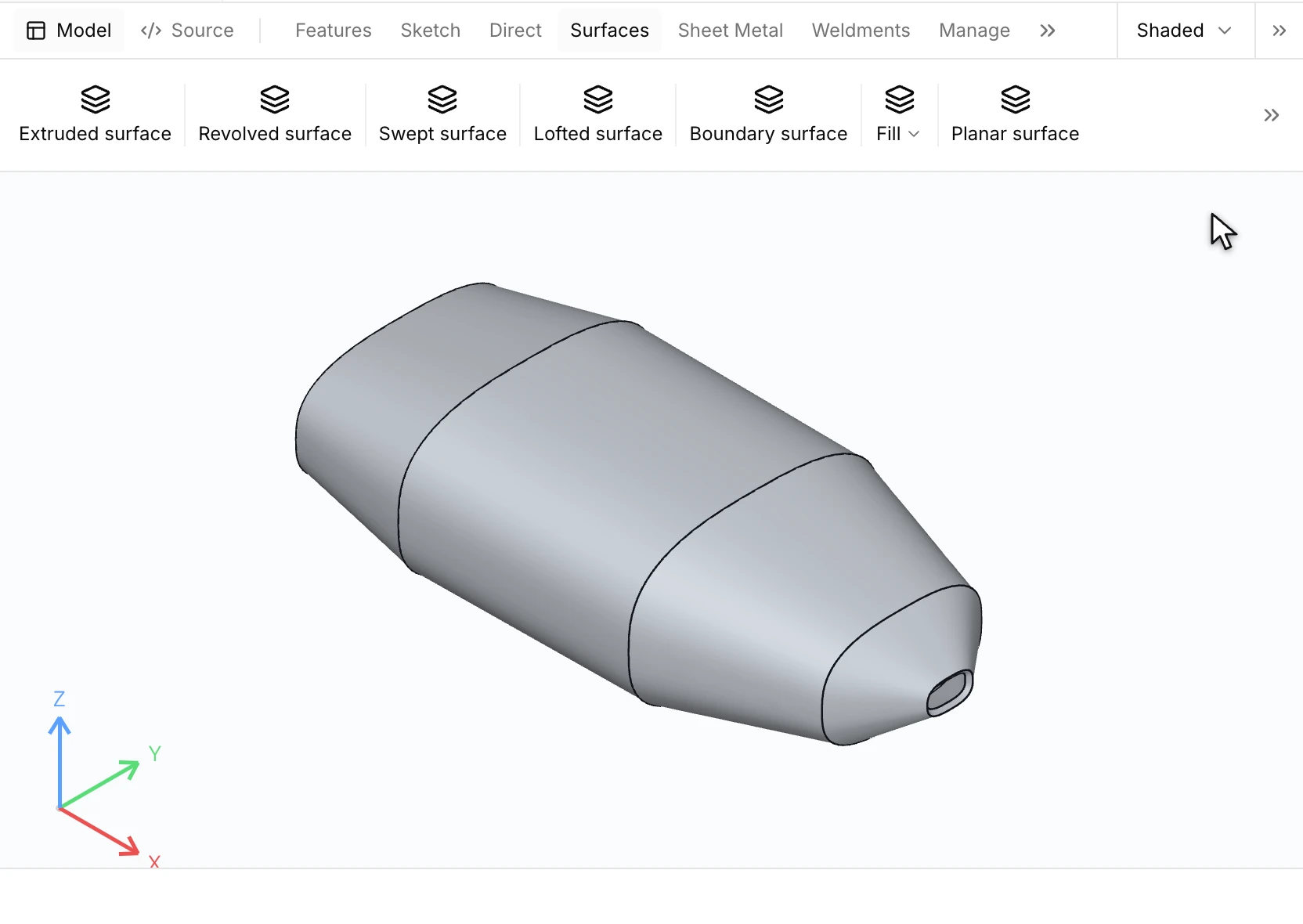
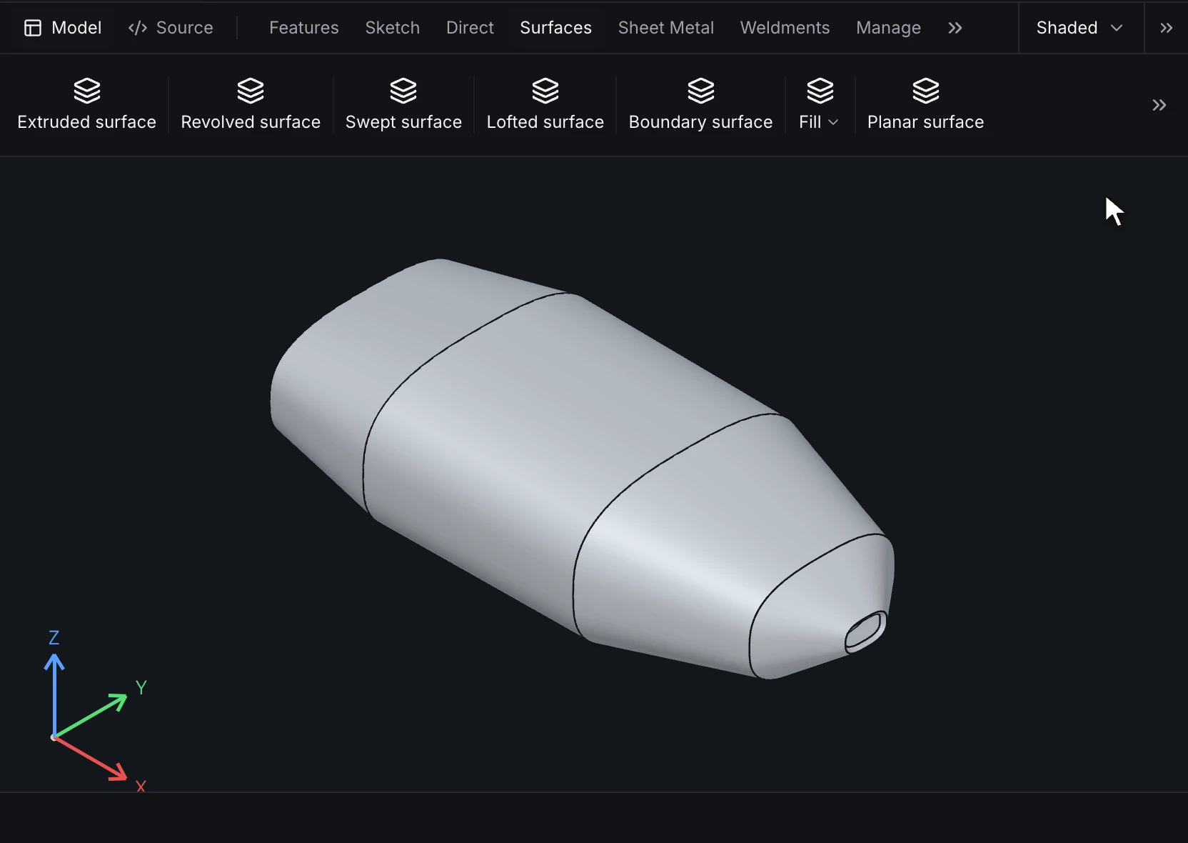
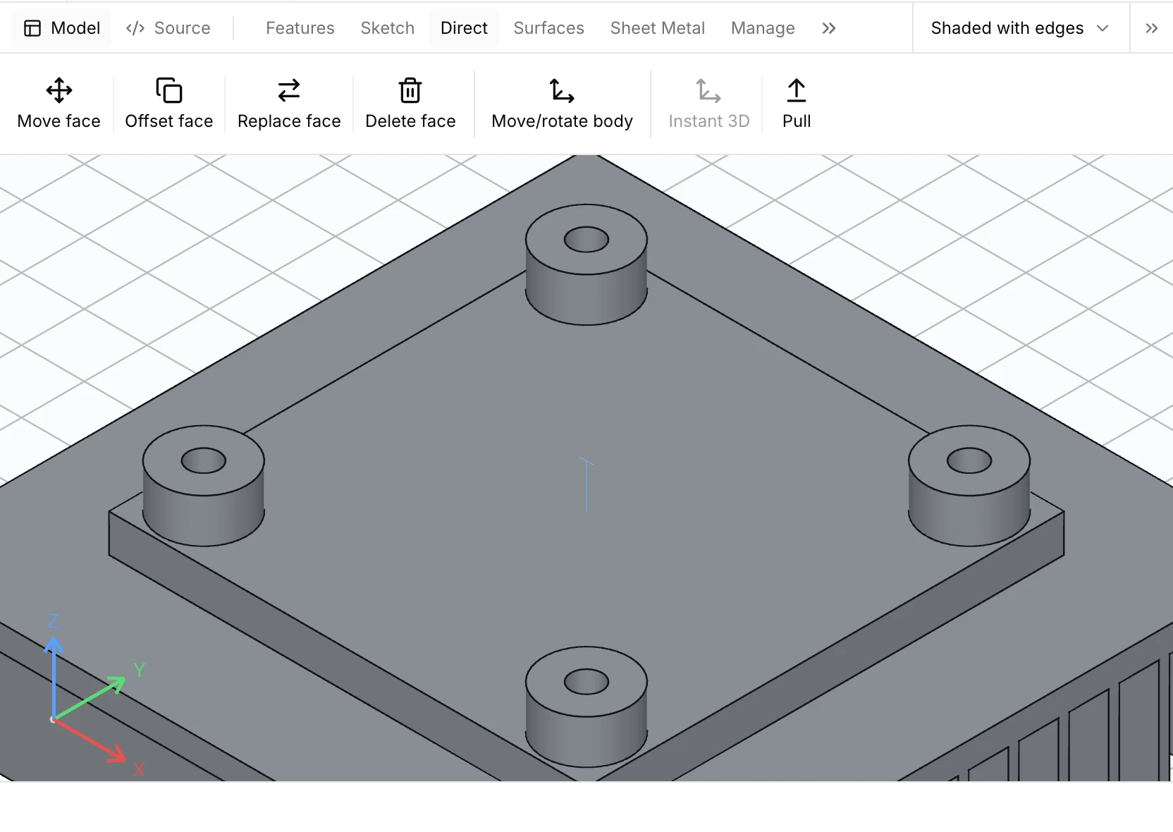
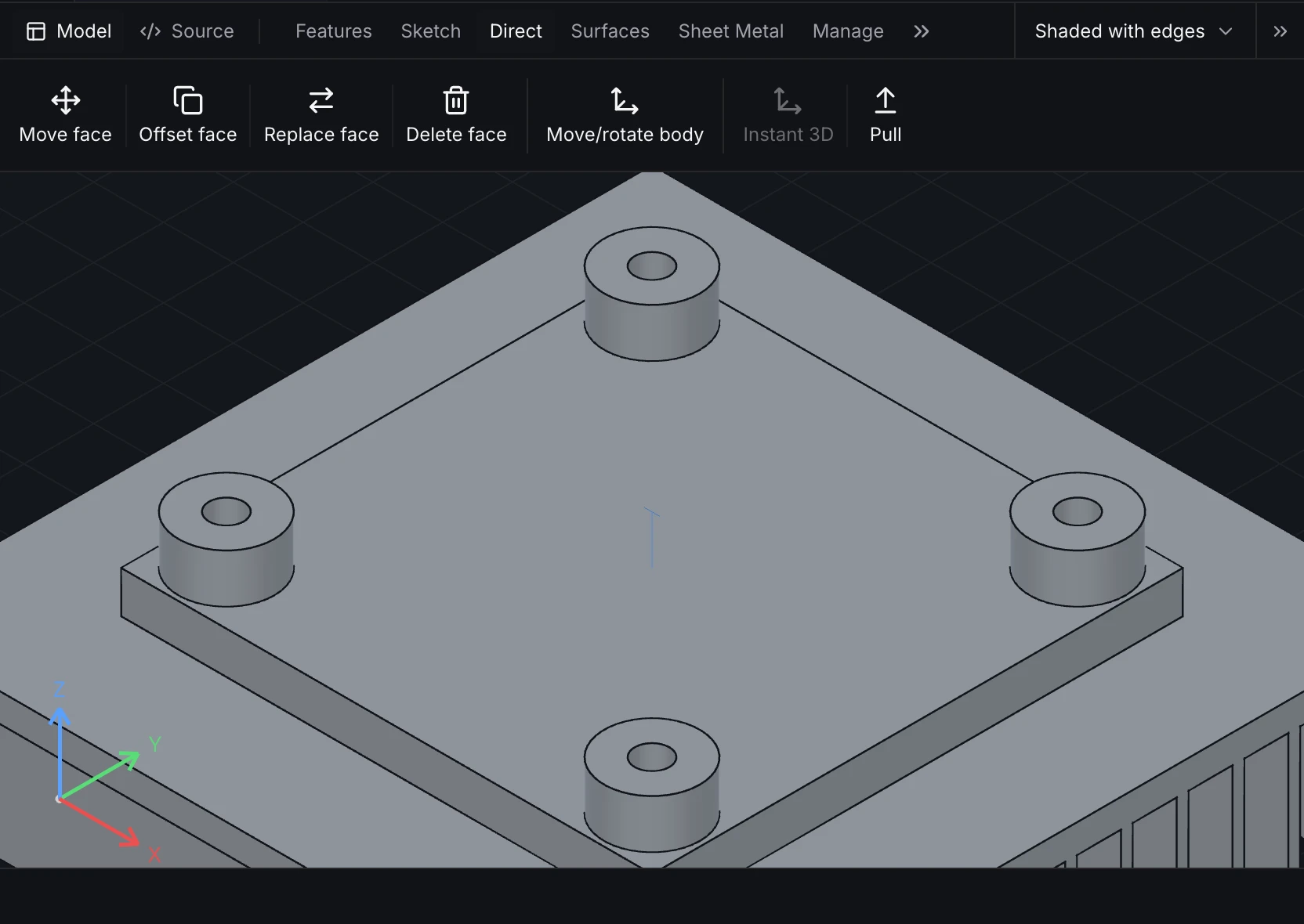
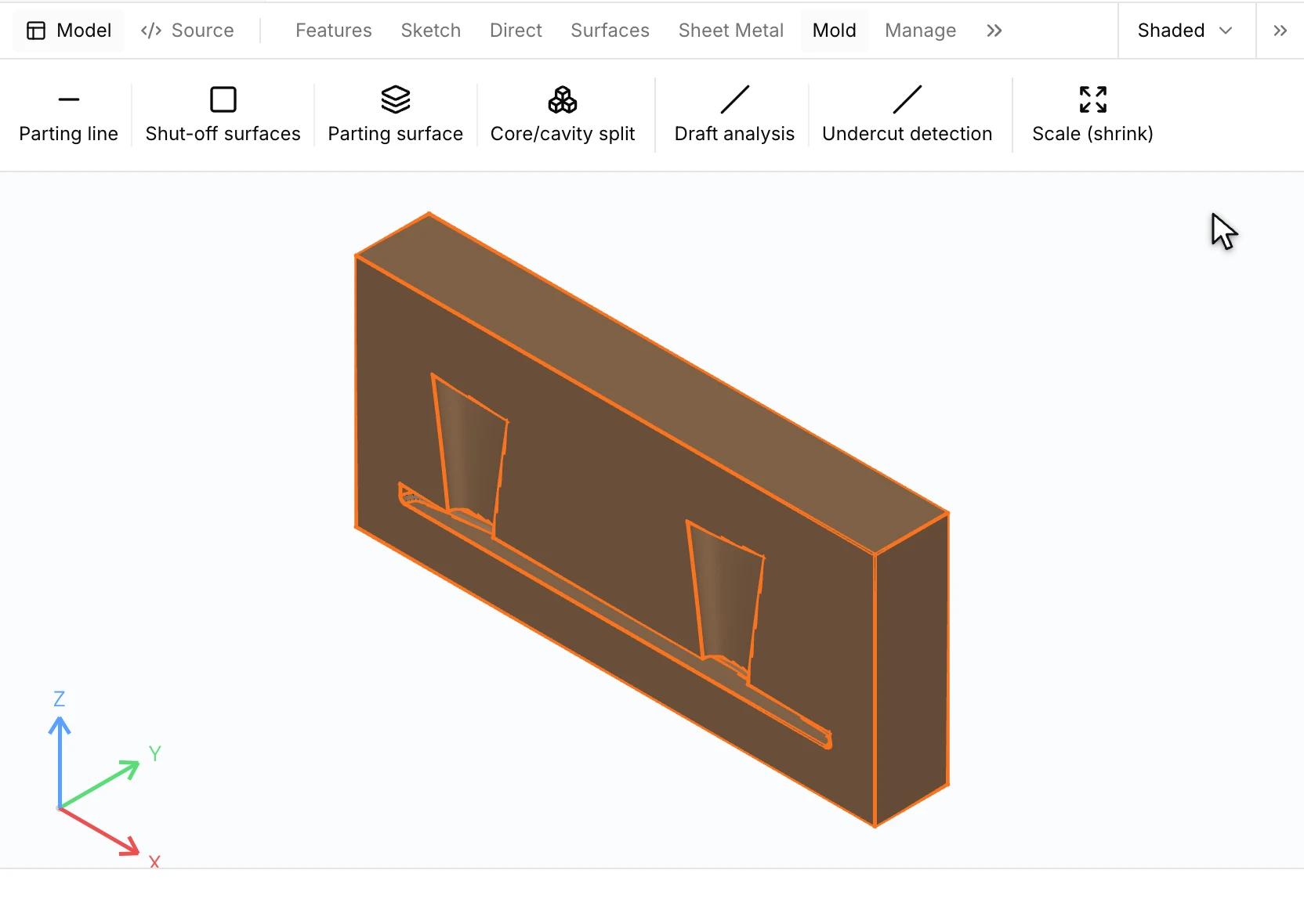
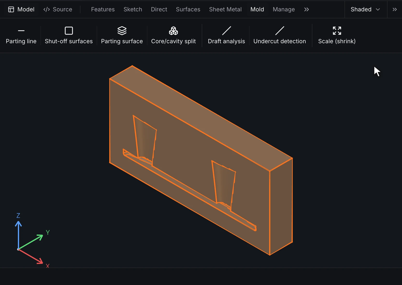
- Surfaces, mold tools, and direct edits recorded as features
- Mass properties, interference and draft checks
Assemblies
- Mates on named faces, edges and points, path mates and mate connectors, with offsets and limits
- Bill of materials from part properties
- Interference, clearance and motion
- Exploded views and top-down skeleton parts
Drawings
- Projected, section, detail, auxiliary and broken-out views
- Dimensions, hole callouts and GD&T to ISO or ASME
- Parts lists, hole, revision and bend tables, general notes and custom sheet sizes
- PDF, SVG, DXF and DWG at true scale
Import
- Open STEP, IGES and BREP files as exact geometry
- Face, body and color names from STEP files that carry them, so mates and studies can select faces by name
- Feature recognition rebuilds holes, fillets, chamfers and extrusions as editable features
- Add features on top of an imported body, which keeps its STEP file as the source
Export
- STEP AP242 with names and semantic PMI
- STL, 3MF, glTF and DXF
- Drawings as PDF, SVG, DXF and DWG at true scale
Familiar shortcuts and standards compliant
Shortcuts you know
Pick the SOLIDWORKS or Onshape keymap in Settings, and the sketch, feature, mate and view shortcuts match the ones you use now. Choose which mouse button orbits and which pans, and zoom goes to the cursor. Right-click a face or an edge for the commands that apply to it, and a selection made first fills the command.
Feature tree and mates
Work in an ordered feature tree with rollback and suppress. SOLIDWORKS mates and Onshape mate connectors map to RunMat mates on named faces, edges and points.
Drawing standards
Dimension and tolerance to ISO or ASME, with GD&T frames, datums and hole callouts, and export PDF, DXF and DWG at true scale.
Exchange standards
Read and write STEP AP242 with names and semantic PMI, plus IGES, BREP, STL, 3MF and glTF, so parts move to and from other tools and suppliers.
Use RunMat with Claude Code, Codex or its built-in agent
Connect Claude Code, Codex or another AI agent through MCP, or use RunMat's built-in agent, a harness built for engineering work. The RunMat Agent guides you through a design: it asks which faces sit against the wall and the thinnest wall your process allows, creates parts from requirements, and checks that a part can be manufactured.
Every change comes back staged as features and dimensions, with the new result beside it, to accept or reject one change at a time. The agent works with virtually any base model, including OpenAI's and Anthropic's.


Start modeling in RunMat
Download the desktop app, or open RunMat in your browser and start from an example.
How does RunMat work?
In RunMat, every part is a plain-text file written for readability. Each click in the model saves to bracket.part, which fits on one screen: three inputs, two sketches, the extrude and the pocket cut, a hole on the top face, an edge fillet, the named faces top and wall, and two configurations. Assemblies and drawings are saved the same way.
Static checks underline unit mistakes and mismatched references in red before anything regenerates, the way a code editor does. That makes a part easy to review line by line, easy to merge, and easy for an AI model to read and edit correctly.
Design languagePart, assembly and drawing filesSimulation study files
use material aluminum from "./materials"part bracket {input width : length = 80 mminput depth : length = 50 mminput thickness : length = 10 mmsketch s1 on origin.xy {l1 = line(start = [0 mm, 0 mm], end = [input.width, 0 mm])l2 = line(start = [input.width, 0 mm], end = [input.width, input.depth])l3 = line(start = [input.width, input.depth], end = [0 mm, input.depth])l4 = line(start = [0 mm, input.depth], end = [0 mm, 0 mm])}feature body = extrude(profile = sketch.s1, distance = input.thickness)sketch s_cut on origin.xy {c1 = line(start = [20 mm, 20 mm], end = [40 mm, 20 mm])c2 = line(start = [40 mm, 20 mm], end = [40 mm, 30 mm])c3 = line(start = [40 mm, 30 mm], end = [20 mm, 30 mm])c4 = line(start = [20 mm, 30 mm], end = [20 mm, 20 mm])}feature cut = extrude(profile = sketch.s_cut, through_all, mode = cut)feature h = hole(face = feature.body.face.end,at = { a = point(60 mm, 10 mm, input.thickness) },diameter = 4 mm,through_all)feature round = fillet(edges = [edges_between(feature.body.face.side(s1.l1), feature.body.face.end)],radius = 1.5 mm)output bracket = { body = feature.body.body, part_number = "BR-100", material = "material.aluminum" }region top : face = { select = [feature.body.face.end], expect = exactly_one }region wall : face = { select = [feature.body.face.side(s1.l4)], expect = exactly_one }publish top = region(region = top)publish wall = region(region = wall)configuration long = { width = 120 mm }configuration analysis = { suppress = [feature.round] }}
FAQ
01Is it parametric?
Yes. A part is defined by inputs with units, constrained sketches and an ordered list of features. Changing an input regenerates the model, and configurations hold variants of one part.
02Can I open my existing CAD files?
Yes, as STEP, IGES or BREP. Parts open as exact geometry, with any face, body and color names the exporting tool wrote into the STEP file. Feature recognition rebuilds holes, fillets, chamfers and extrusions as editable features, and new features can go on top. SOLIDWORKS, Onshape and Fusion all export STEP AP242.
03Which file formats does it read and write?
Native files are .part, .assembly and .drawing. RunMat imports STEP, IGES and BREP, and exports STEP AP242 with names and semantic PMI, STL, 3MF, glTF and DXF. Drawings export to PDF, SVG, DXF and DWG.
04Does it work offline?
Yes. The desktop app models, regenerates, checks, exports and runs simulations on your computer with no internet connection. A network connection may be required for security and permission checks. The browser app runs the same editor.
05Is RunMat MCAD free CAD software?
RunMat MCAD is free in production for individuals, including freelancers; students and faculty at an academic institution, for teaching or research there; contributors to an open-source project, for work on that project; and organizations with 250 or fewer people and US$10M or less in annual revenue. Anyone can evaluate it under the evaluation terms in the RunMat license. Production use at larger organizations needs a Professional seat. Free and Professional include the same MCAD features, and simulations use the plan's weekly physics simulation allowance.
06Can a team self-host RunMat MCAD?
Enterprise covers self-hosted RunMat servers, including air-gapped networks, with SSO, SAML and SCIM and audit controls. On Free and Professional, projects live on each person's computer or in RunMat cloud projects.
07Can AI models edit parts?
Yes. The in-app agent, Claude Code, Codex and other AI agents can open, edit, check and render parts, assemblies and drawings, and launch simulations on them. Their changes are staged as features and dimensions for you to accept or reject.