
What is finite element analysis (FEA)?
Finite element analysis (FEA) predicts how a physical part responds to loads, heat, current, sound, or flow by dividing its shape into many small pieces, called elements, and solving the equations of physics on all of them together. The result is a field over the whole part: a displacement and stress at every point of a bracket, a temperature everywhere in a heat sink, or a pressure throughout a duct.
The finite element method (FEM) is the mathematics: the governing equation is written in an integral, or weak, form and approximated by simple functions on each element. Finite element analysis is the engineering use of it on a real part.
Engineers use FEA when a part's shape is too complex for a hand formula, to find where it is most highly stressed, how much it deflects, what its natural frequencies are, or how hot it runs, before anything is built.
What questions does FEA answer?
| Question | Analysis | Typical result |
|---|---|---|
| Will this part yield or deflect too far under its working load? | Linear static | Displacement, stress, reaction forces |
| At what frequencies will it resonate? | Modal | Natural frequencies and mode shapes |
| At what load will a slender part buckle? | Buckling | Critical load factor and buckled shape |
| How does it respond to a shock, an impact or a time-varying load? | Transient | Displacement and stress over time |
| How does it respond to vibration at each frequency, or to a random vibration spectrum? | Harmonic, random response | Response amplitude, RMS stress |
| How hot does it get, and where does the heat go? | Steady or transient thermal | Temperature, heat flux |
| How much stress does uneven heating cause? | Thermal stress | Thermal strain and stress |
| Where does current flow, and how much heat does it produce? | Electromagnetic, Joule heating | Potential, current density, resistive loss |
| What sound pressure builds up in an enclosure or duct? | Acoustic | Sound pressure and level |
| What is the pressure drop and velocity through a channel? | Fluid flow (finite volume in RunMat) | Velocity, pressure, flow rate |
How does FEA work?
Every finite element analysis follows the same six steps.
- Geometry. Start from the part's exact shape, usually a CAD file such as STEP. Name the regions the analysis refers to: the solid body, the face that is bolted down, the face that carries the load.
- Mesh. Divide the volume into elements, most often tetrahedra. Each element has nodes at its corners, and quadratic elements add nodes at the middle of each edge. Smaller elements follow the geometry and the solution more closely and cost more to solve.
- Material. Give each region its properties: Young's modulus, Poisson's ratio and density for a structural analysis; conductivity and specific heat for a thermal one.
- Loads and supports. Apply what the part experiences: forces, pressures, gravity, heat input, convection, voltages. Fix what holds it in place. These are the boundary conditions.
- Solve. Inside each element, the unknown (displacement, temperature, pressure) is approximated by simple polynomial shape functions of the node values. Writing the governing equation in that form for every element and adding the elements together gives one large, sparse system of equations, solved for the unknown at every node.
- Results. Inspect the fields on the part, read values at the places that matter, and check them: do the reaction forces balance the applied load, do the deflections make physical sense, and does the answer stop changing when the mesh is refined?
For a linear static analysis the system is
where is the stiffness matrix assembled from every element, holds the applied loads, and is the displacement of every node. A solver finds ; strain and stress follow from its derivatives.
The same idea extends to other physics. A thermal analysis assembles a conductivity matrix and solves for temperature; a modal analysis assembles stiffness and mass matrices and solves an eigenvalue problem for the natural frequencies and mode shapes .
A worked example: a steel cantilever
A 1 m steel beam with a 100 mm square section is fixed at one end. A 100 kPa downward traction on the free end face adds up to 1 kN. Beam theory gives the tip deflection as
and the bending stress on the top surface as with : 6.0 MPa at the support and 5.40 MPa at x = 100 mm.
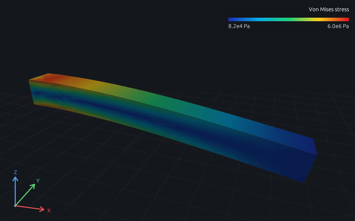
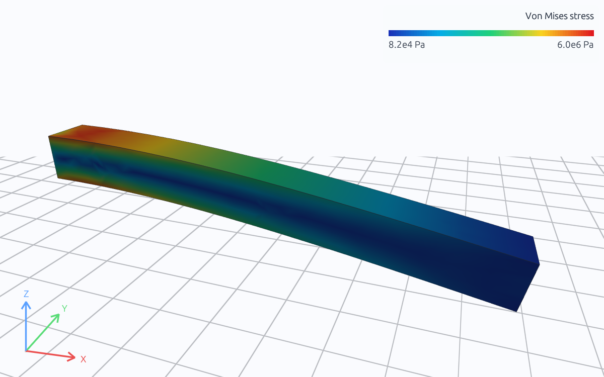
Von Mises stress · Pa · 8.25e+4 to 6.02e+6. Drag to rotate; scroll to zoom.
The figure above is a RunMat solve of this beam on quadratic tetrahedra. Its tip deflection is 0.2000 mm, and the top-surface stress at x = 100 mm is 5.43 MPa, within 0.6 % of beam theory. The model part of the study, the supports and the load, is a few lines of text:
model loaded_beam {
    assign material.steel to geometry.beam.region.body
    constraint fixed_end {
        structural.fixed { target = geometry.beam.region.fixed_end }
    }
    load end_traction {
        traction on geometry.beam.region.loaded_end = [0, 0, -100000] Pa
    }
    load_case service { include load.end_traction }
}
The linear static guide walks through the complete study, which you can download and run.
Why does element order matter?
A linear tetrahedron (Tet4) has four corner nodes, so the displacement inside it varies linearly and its strain and stress are constant. Bending needs strain that changes through the thickness, so a coarse linear mesh is too stiff: it under-predicts deflection. A quadratic tetrahedron (Tet10) adds a node at the middle of each edge, can bend, and places those nodes on the exact curved CAD surface.
| Mesh of the cantilever | Tip deflection | Against beam theory |
|---|---|---|
| Linear tetrahedra (Tet4), 150 mm, 431 nodes | 0.1007 mm | −50 % |
| Linear tetrahedra (Tet4), 50 mm, 729 nodes | 0.1625 mm | −19 % |
| Quadratic tetrahedra (Tet10), 150 mm, 2,727 nodes | 0.2000 mm | +0.02 % |
| Quadratic tetrahedra (Tet10), 50 mm, 4,679 nodes | 0.2005 mm | +0.2 % |
Quadratic elements are the usual choice for stress and vibration. Linear elements are cheaper and are often adequate for temperature, where the field is smoother. Thin walls and slender frames can also be modeled with shell and beam elements, which carry bending through a declared thickness or section instead of many solid elements through it.
How do you know the mesh is fine enough?
Solve the same study on progressively finer meshes and watch the quantity you care about. When it stops changing, the mesh is fine enough for that quantity. Different quantities converge at different rates: deflection depends on the whole beam and settles early, while peak stress depends on a small region and needs more elements there.
| Requested element size (Tet10) | Nodes | Tip deflection | Top-surface stress at x = 100 mm | Largest element stress |
|---|---|---|---|---|
| 150 mm | 2,727 | 0.2000 mm | 5.43 MPa | 5.39 MPa |
| 50 mm | 4,679 | 0.2005 mm | 5.41 MPa | 5.27 MPa |
| 25 mm | 32,075 | 0.2007 mm | 5.41 MPa | 5.76 MPa |
The deflection and the stress at x = 100 mm settle within 0.4 %. The largest element stress does not: it sits at the fixed edge, where a perfectly rigid support meets a free surface. That is a singularity, where the exact stress is unbounded, so the computed value keeps changing as the elements shrink. Read stress a short distance from such points, or model the real fillet and support stiffness. The mesh refinement guide works through a convergence study step by step.
What does FEA assume?
An analysis answers the question its inputs describe. Common sources of error are:
- Supports. A fixed face is perfectly rigid; real bolts, welds and clamps flex. Over-constraining a part makes it stiffer and moves its stress.
- Loads. A load applied to a face is spread over that face; a point load in a model creates an infinite local stress that real contact does not.
- Material. Linear elastic analysis assumes stress stays below yield and strain stays small. Beyond that, a nonlinear analysis with a plasticity model is needed.
- Units. A part drawn in millimeters and read as meters is a thousand times larger. RunMat checks units on every value and rejects a force where a pressure belongs.
- Geometry. Small fillets, holes and thin walls change local stress; removing them speeds up the solve and changes the answer near them.
Verification and validation
Verification asks whether the equations were solved correctly: does the mesh converge, do the reactions balance the loads, does a simple case match a known answer such as the beam formula above? Validation asks whether those were the right equations for the real part: do the predictions match a test? Both are needed before a result supports a design decision. See validation methodology for how RunMat records both.
Finite element analysis in RunMat
In RunMat a complete analysis is a .fea text file: geometry from a STEP file, a mesh, materials,
loads and supports, and the analyses to run. runmat check checks units, regions and every
reference before anything is meshed, and runmat run meshes, solves and saves the result,
which you can read and plot from .m code.
runmat check cantilever-static.fea
runmat run cantilever-static.fea
Continue with the linear static guide, the physics reference, meshing, or the structural, thermal and other physics pages.