Design and simulate circuit boards, from schematic to fabrication
Draw schematics, lay out and route boards, and check them in 3D, on your desktop or in the browser.


Schematic capture and PCB layout
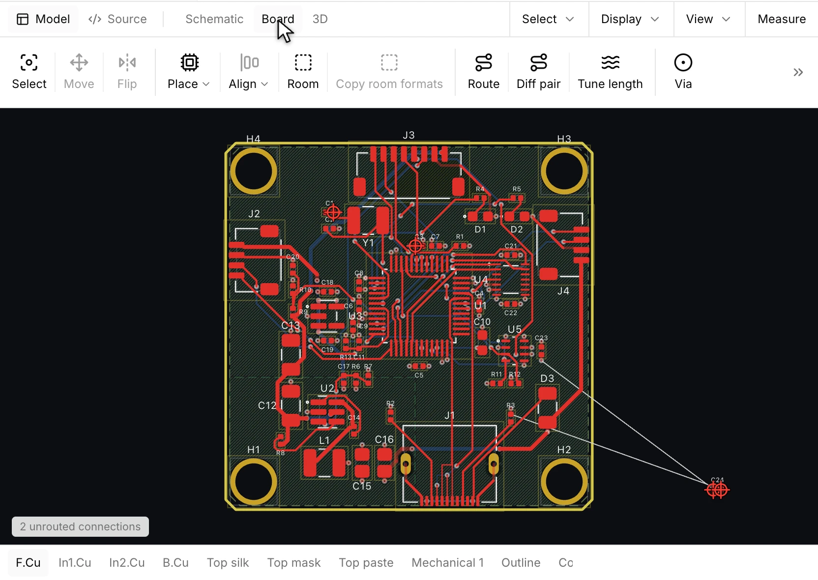
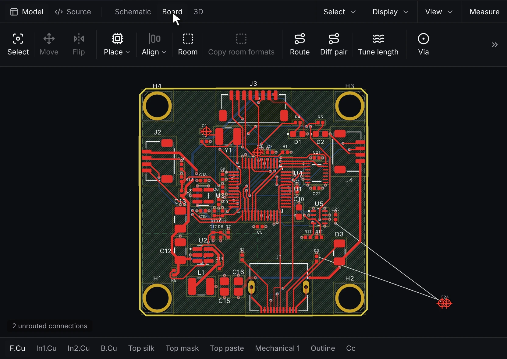
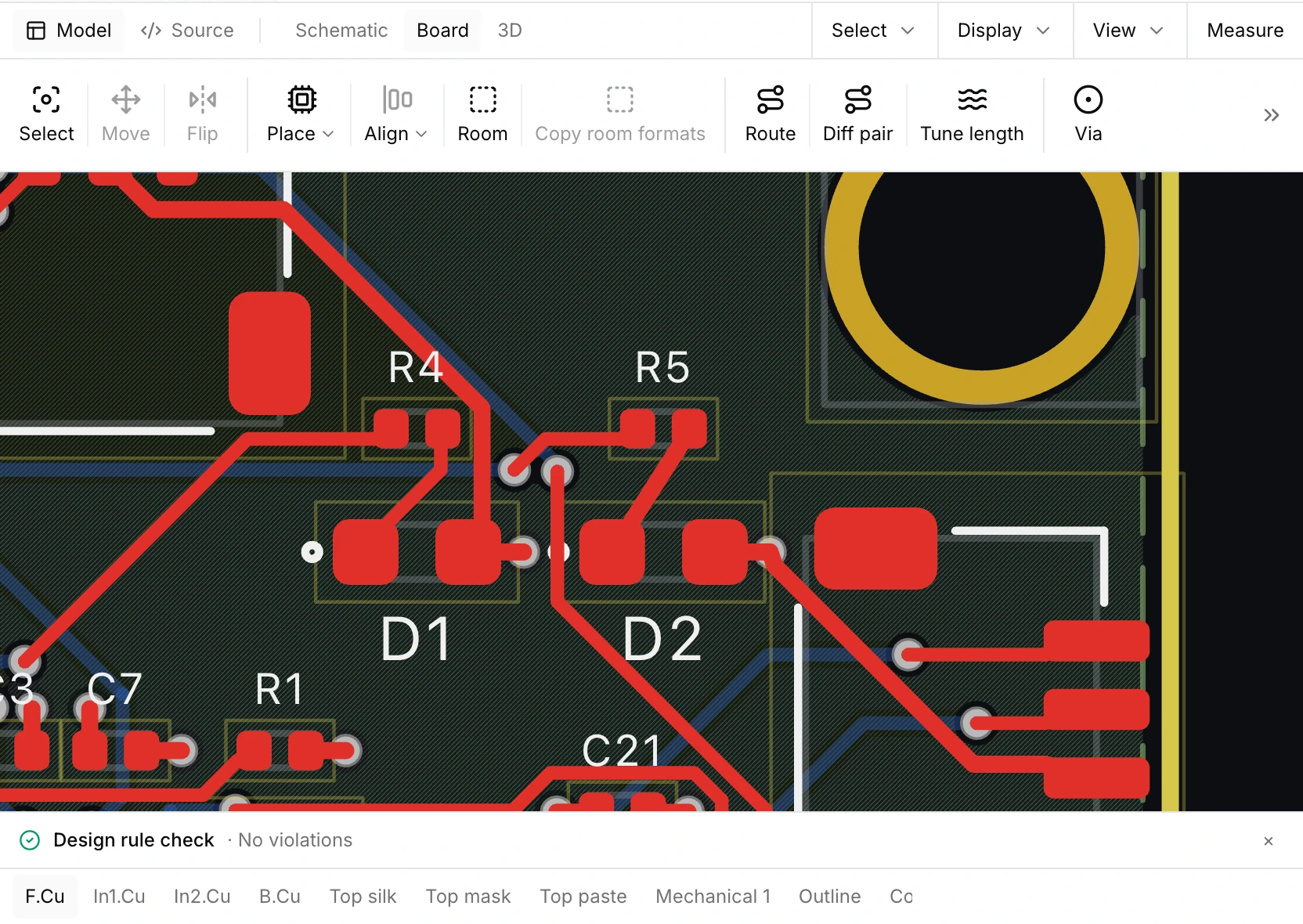
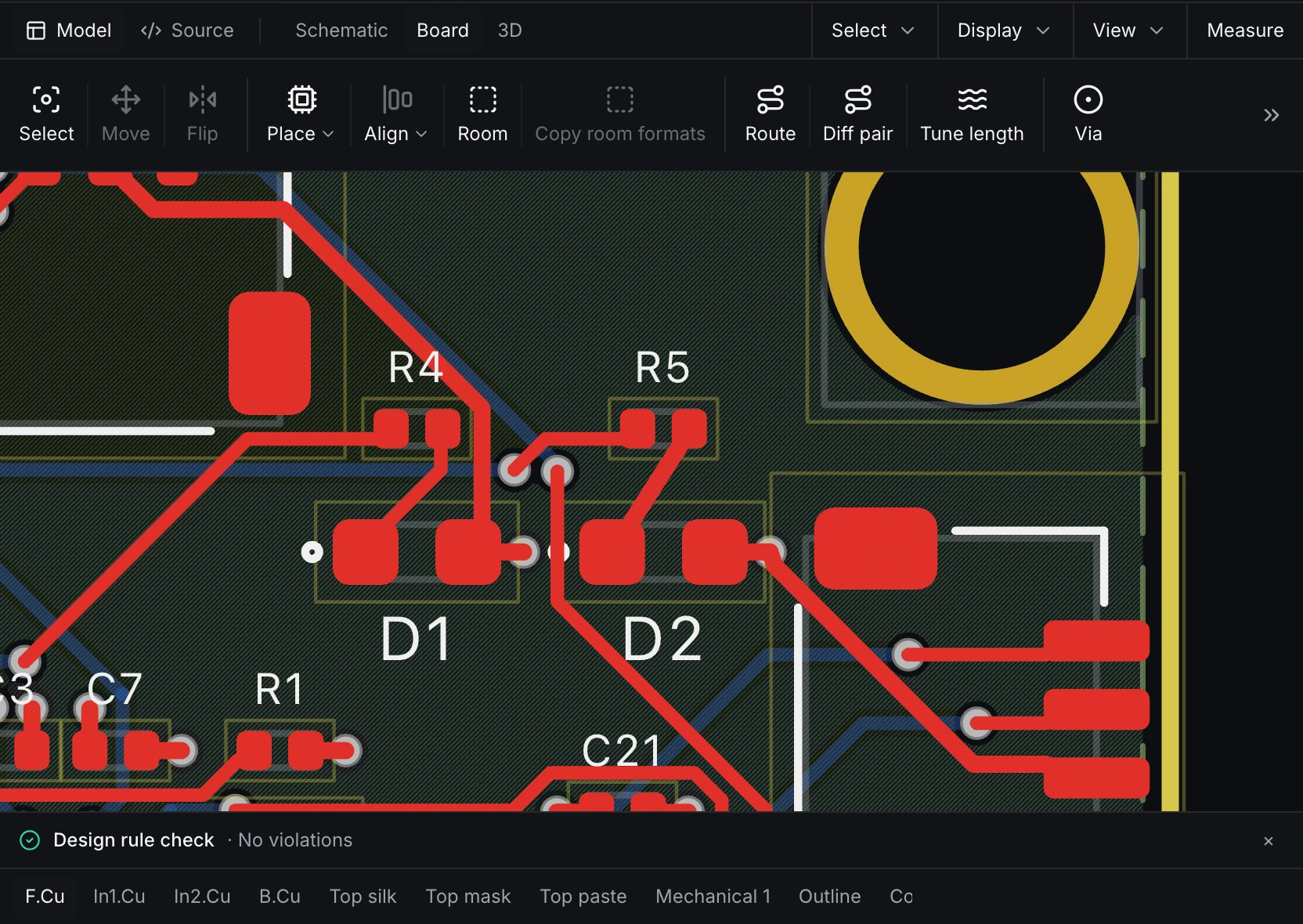
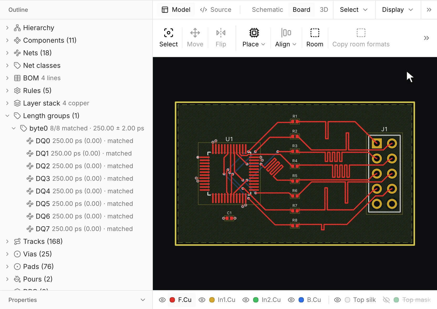
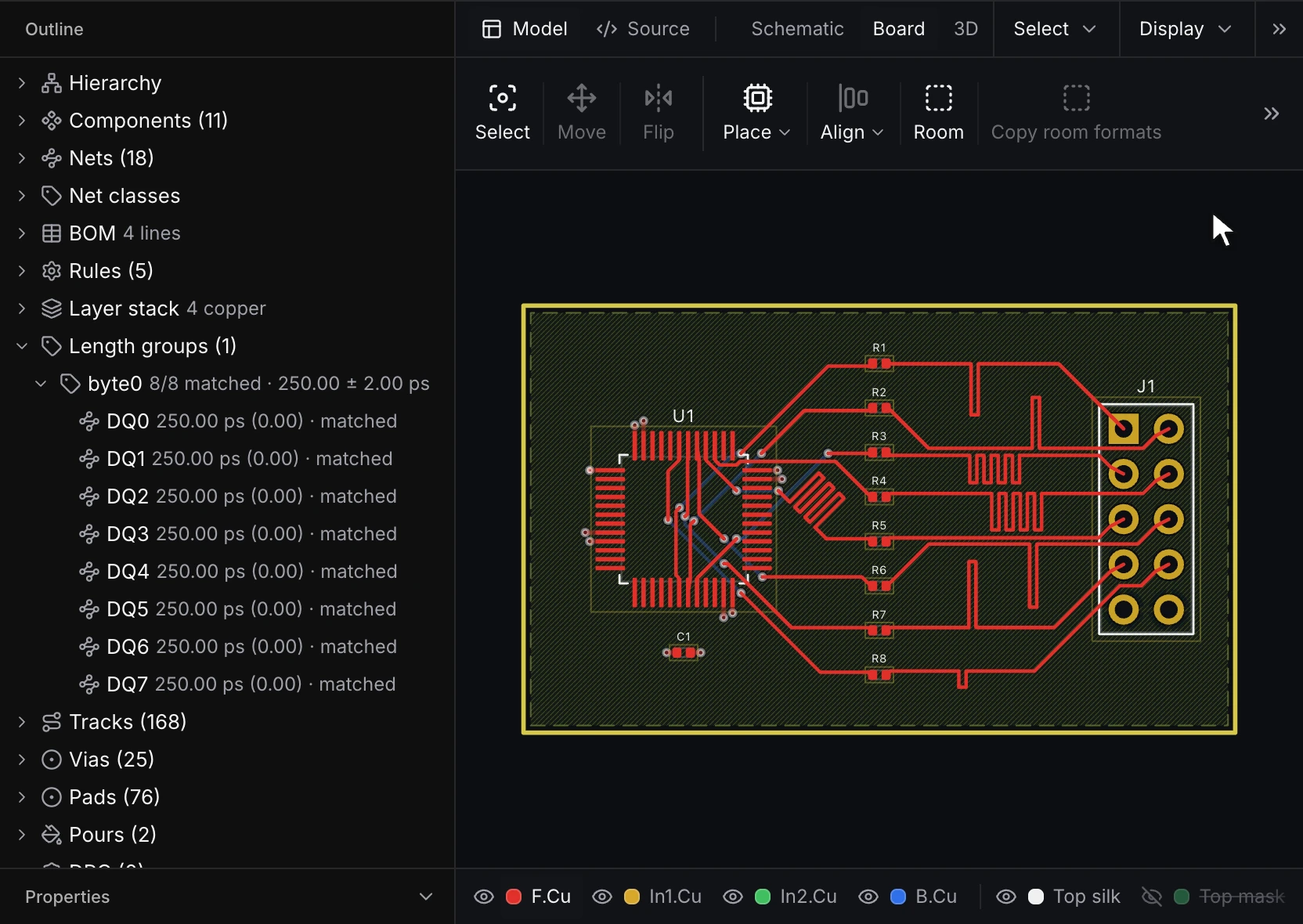
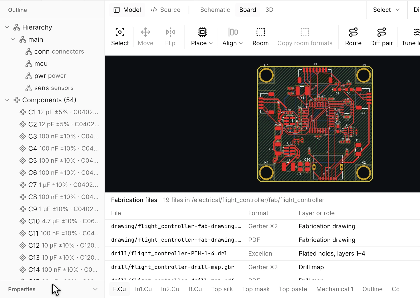
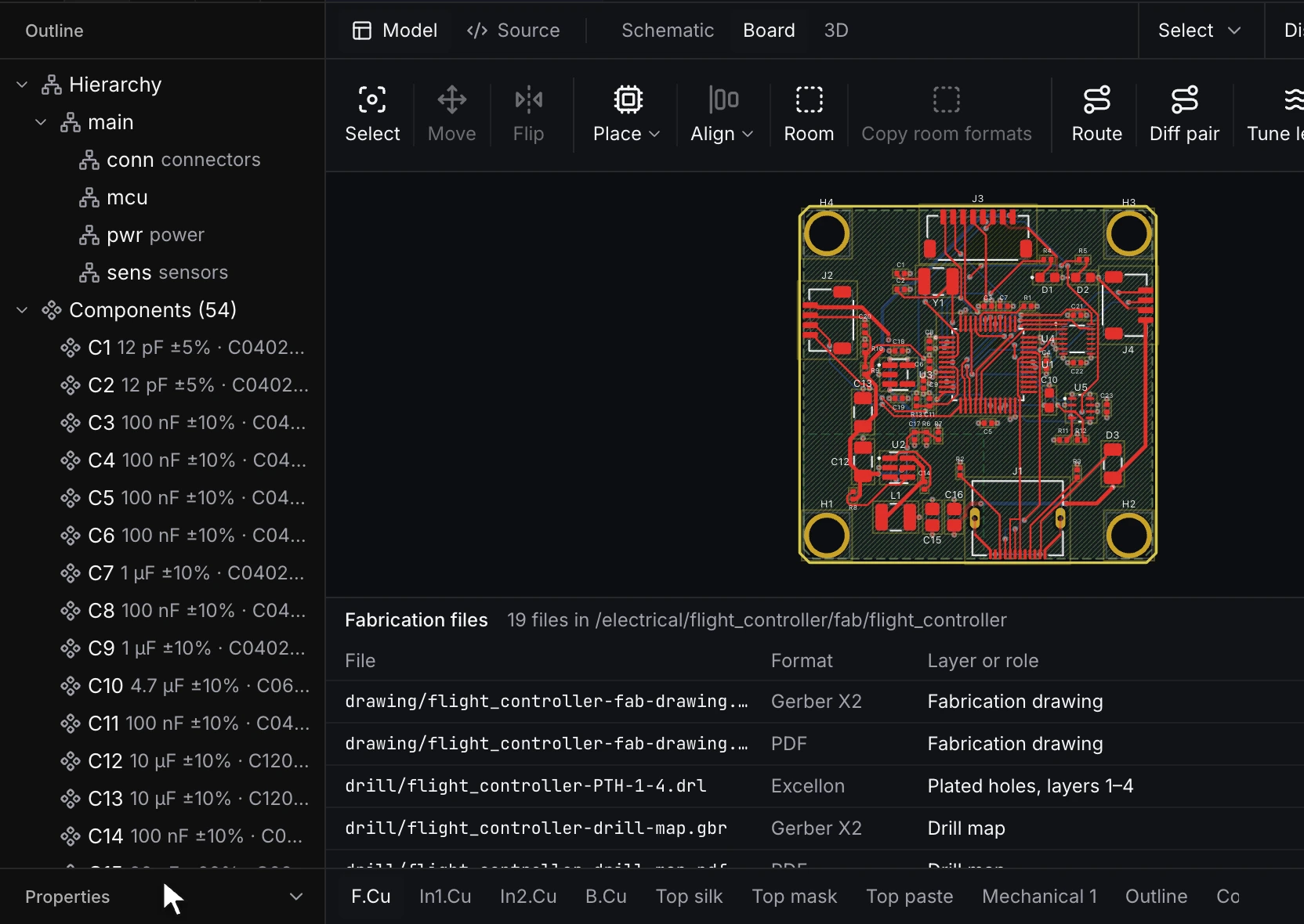
RunMat has all the PCB tools you need to make modern boards: draw the schematic, choose parts, place and route the board, check it against its rules, write the fabrication files and see it in 3D. ERC and DRC run as you edit.
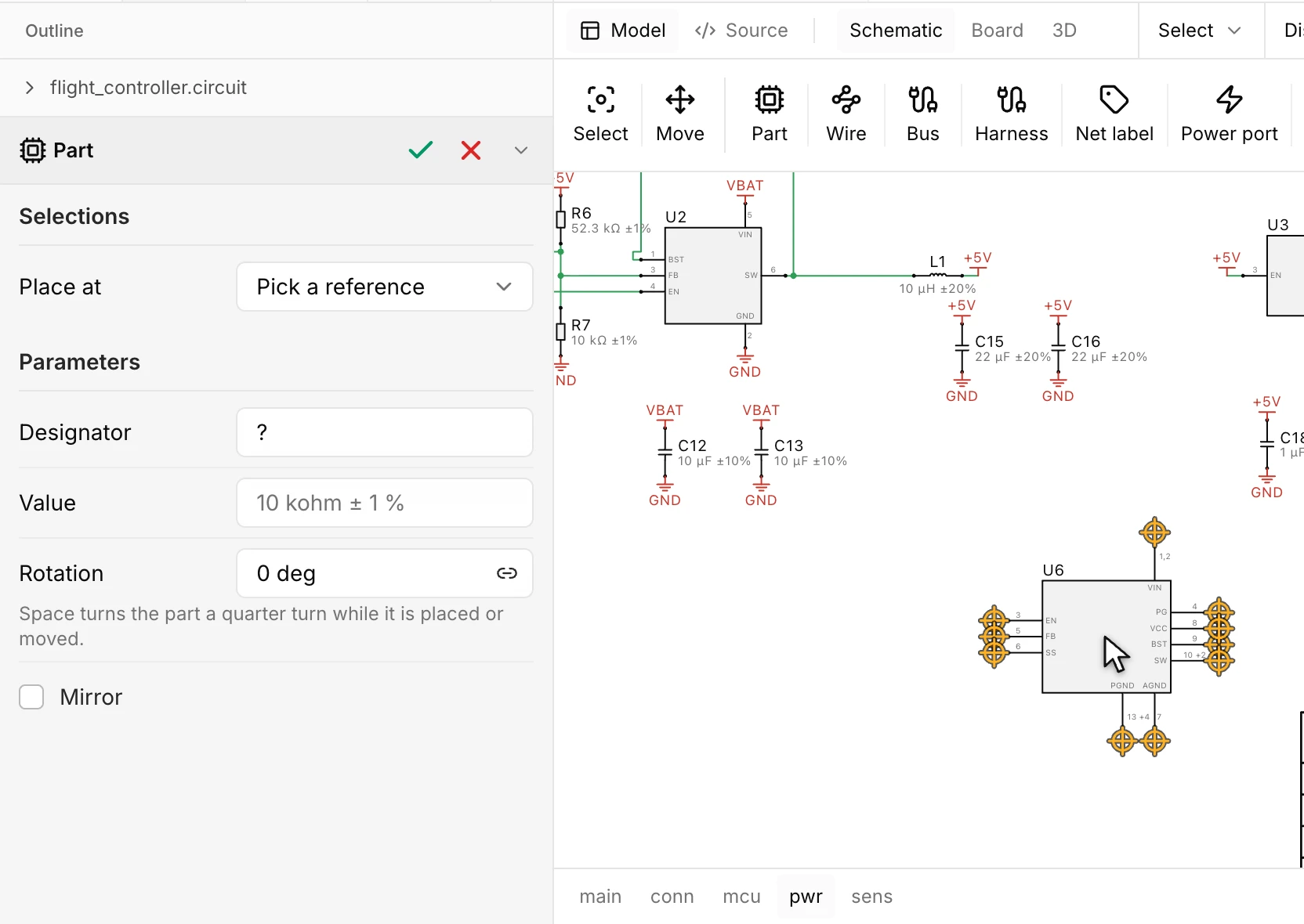
Draw hierarchical schematics
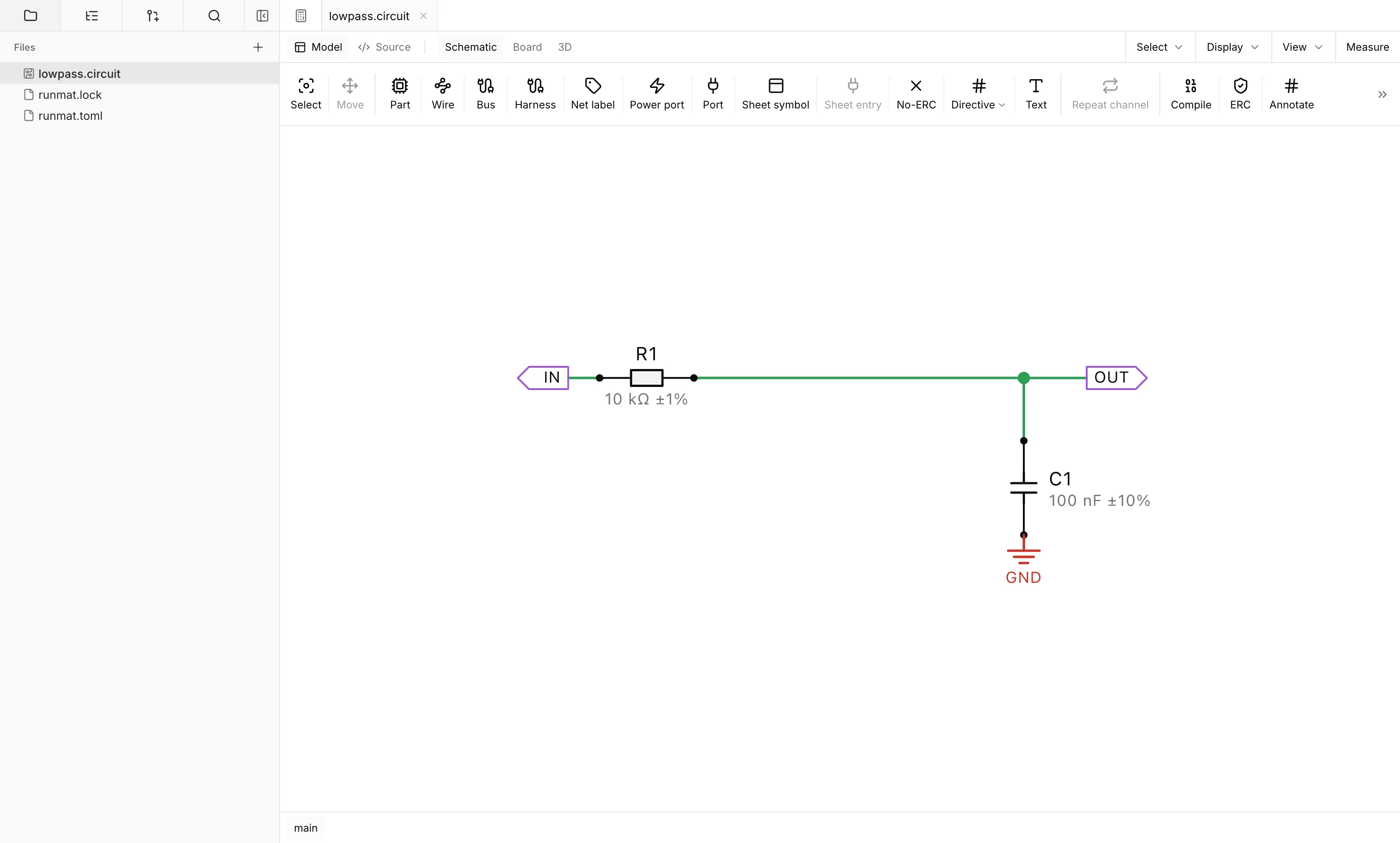
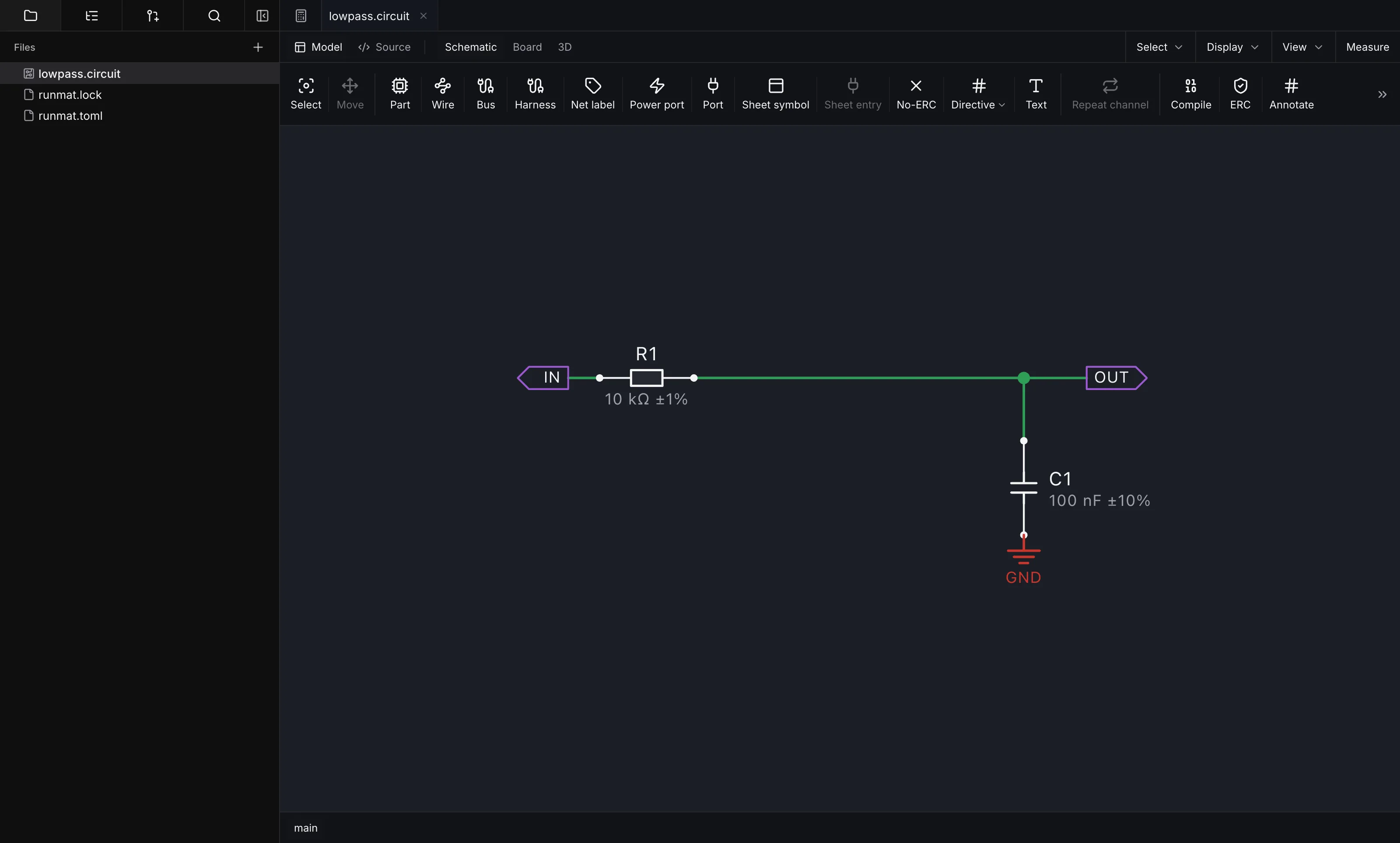
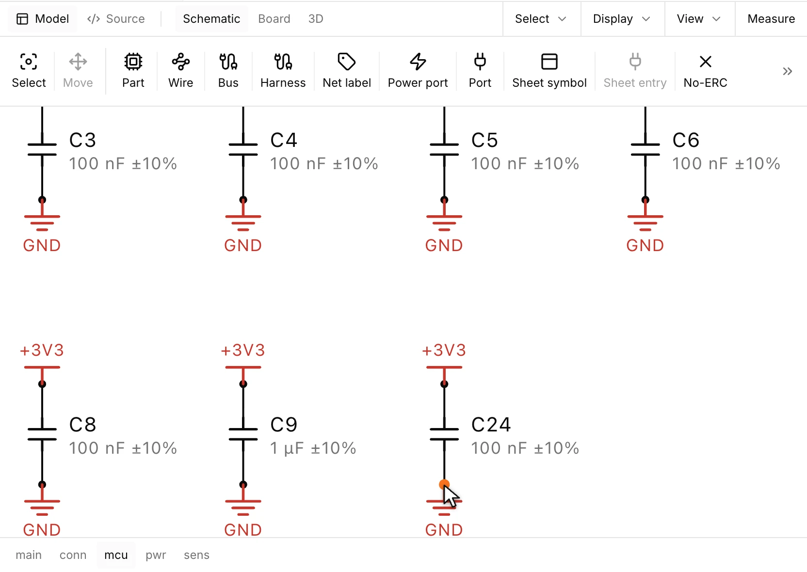
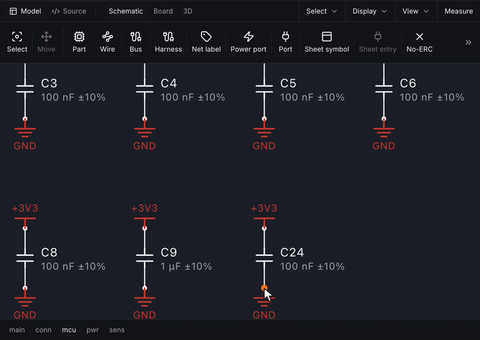
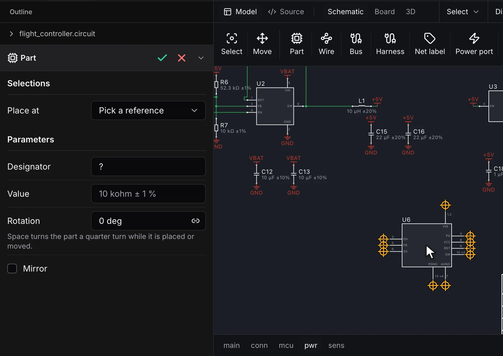
Place parts, wire them and label nets on hierarchical sheets. Draw an amplifier channel once, repeat it and bind the copies to a bus, so a fix to the channel sheet reaches every copy.
- Part, wire, bus, harness, net label, power port and port
- Hierarchical sheets with sheet symbols and sheet entries
- Repeated channels bound to a bus, and large parts split into units
- Compile, ERC with no-ERC markers, and annotate
- Engineering change orders (ECOs) to the board and back, reviewed change by change
Run circuit and multiphysics simulations before fabrication
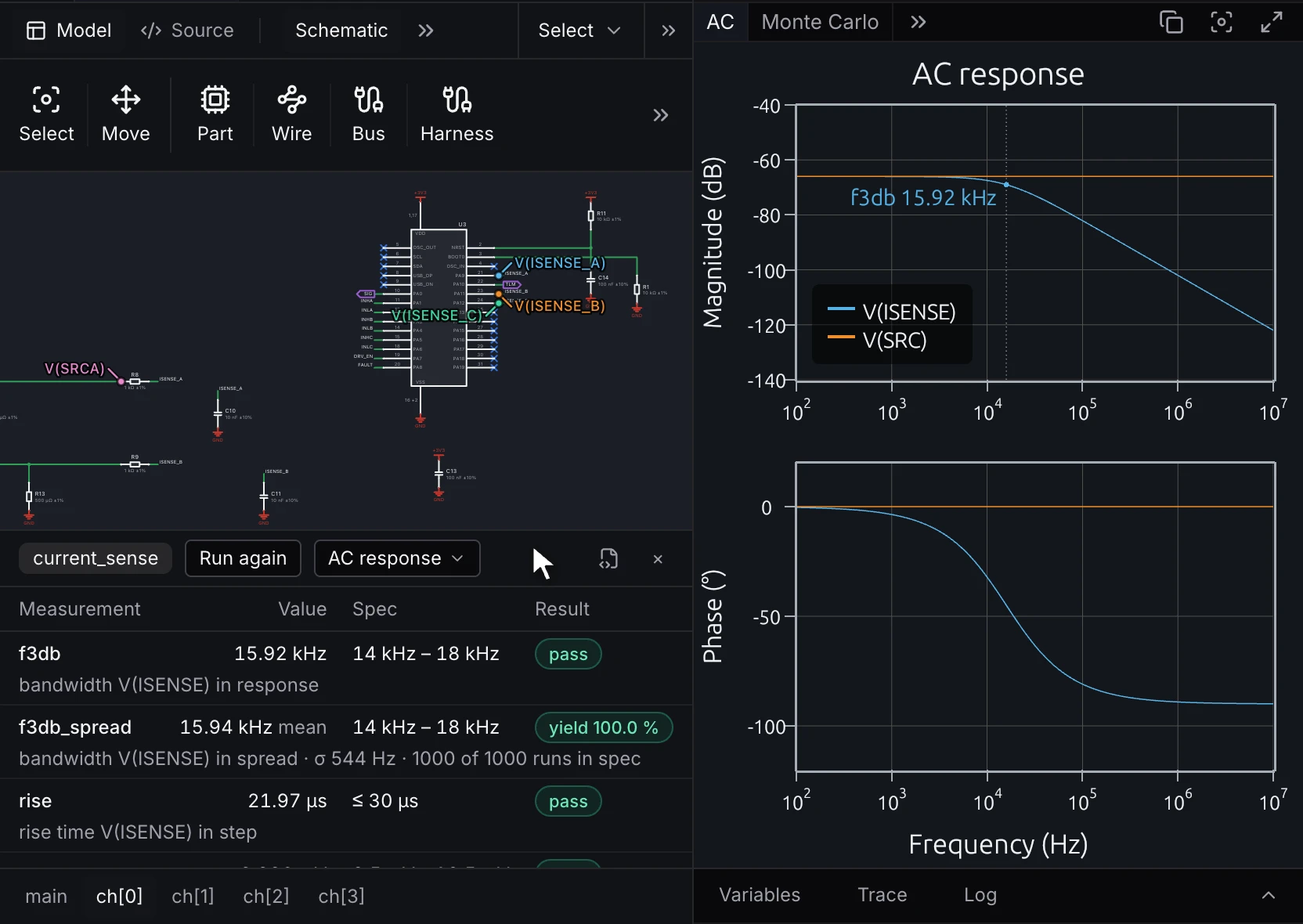
Find hot spots, IR drop and warpage, and check the circuit against its spec, while the board is still a design and before you pay for a fabrication run. Board studies read the board you laid out, and circuit simulations run from probes on the schematic.
Measure against the spec
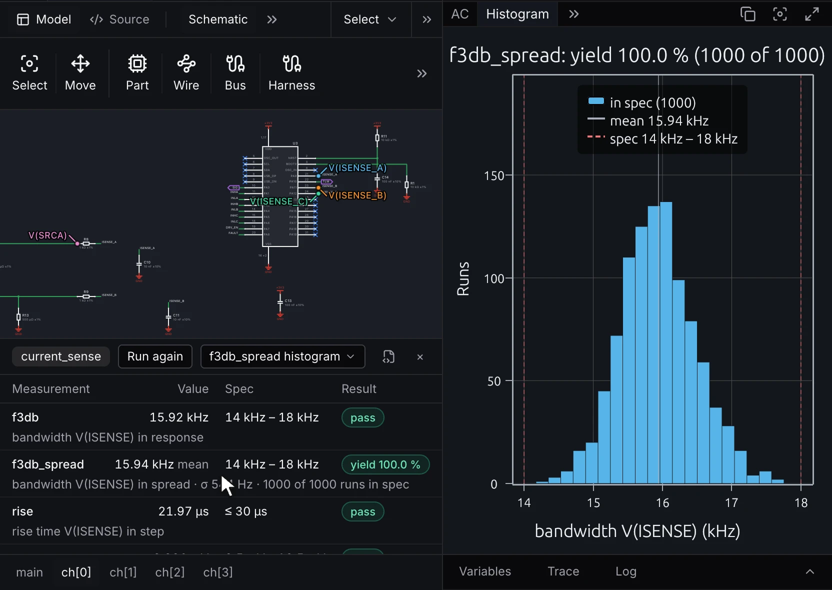
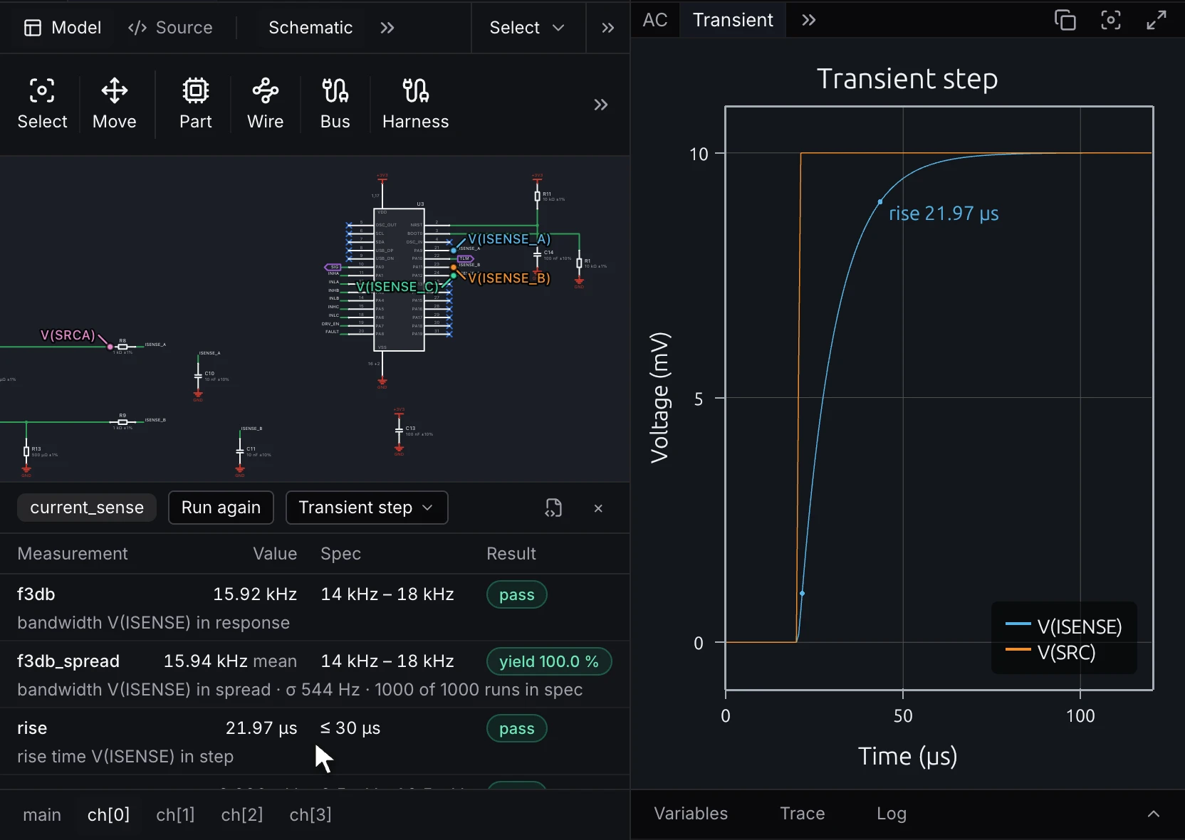
The channel's AC response gives its bandwidth at the −3 dB point: 156.7 kHz against a spec of 152 to 166 kHz. The measurements, the part tolerances and the plot sit beside the schematic they came from.
- Operating point, DC sweep, AC and noise analyses
- Bandwidth, unity-gain frequency, phase margin and Q
- Gain and phase at a frequency, and output and input-referred noise
- Each measurement checked against its spec



PCB design capabilities
Libraries and parts
- KiCad symbol and footprint libraries opened in place
- Manufacturer part search with stock, price and lifecycle
- SPICE models in SPICE3, PSpice or LTspice syntax on any part
- Variants with fitted and not-fitted parts
Layers and routing
- Multilayer stackups, with impedance and thermal properties
- Differential pairs, length tuning, BGA fanout and teardrops
- Pours, split planes and stitching vias
- Rooms, keepouts, test points and panelization
High-speed design
- Impedance-controlled net classes that set track width and pair gap per layer from the stackup
- Matched-length groups and in-pair skew, tuned by length or by delay in picoseconds
- Lengths measured through series resistors and other parts on the net
- Trace impedance field-solved on the board's cross-section, with solder mask and etch shape
- Via stub limits and back-drilling, with a back-drill file for each drill face
- Return-path checks where a controlled track crosses a split in its reference plane
Checks
- ERC while you draw, with no-ERC markers
- ECOs from schematic to board and back, reviewed before they reach copper
- Live DRC against the board house's capability rules
- Review checks for USB Type-C receptacles, switching regulators, decoupling and I²C pull-ups
runmat testruns checks and simulations in CI
Simulation
- Operating point, DC sweep, AC, noise and transient
- Parameter sweeps and Monte Carlo over tolerances
- Board temperature with two-resistor package models
- DC IR drop and warpage
Import
- Open KiCad 9 and 10 projects with hierarchy, symbols, footprints, net classes, custom rules, stackup, tracks and zones
- Save back as KiCad with the same netlist, rules and copper, with a list of any item not carried
- Import again after changes in KiCad, and the RunMat project updates in place
- Altium Designer, EAGLE and EasyEDA projects with their schematics, boards and libraries
Netlist formats and BOM
- Netlists in KiCad, SPICE, EDIF 2.0 and IPC-D-356A formats
- BOM per variant, with manufacturer part numbers
- Annotation and PDF schematic sets
Fabrication outputs
- Gerber X2, ODB++ and IPC-2581
- NC drill and pick-and-place
- Assembly and fabrication drawings
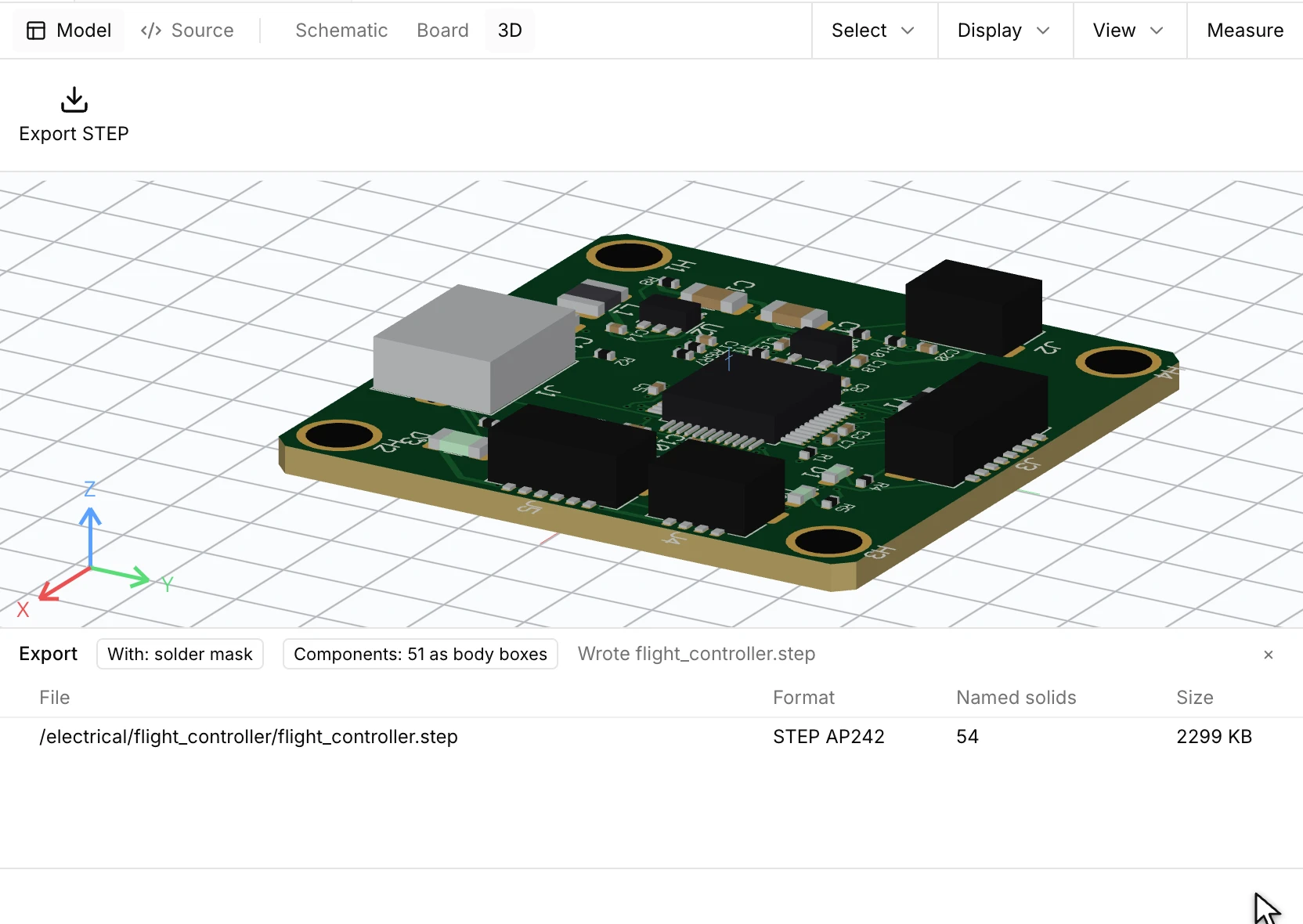
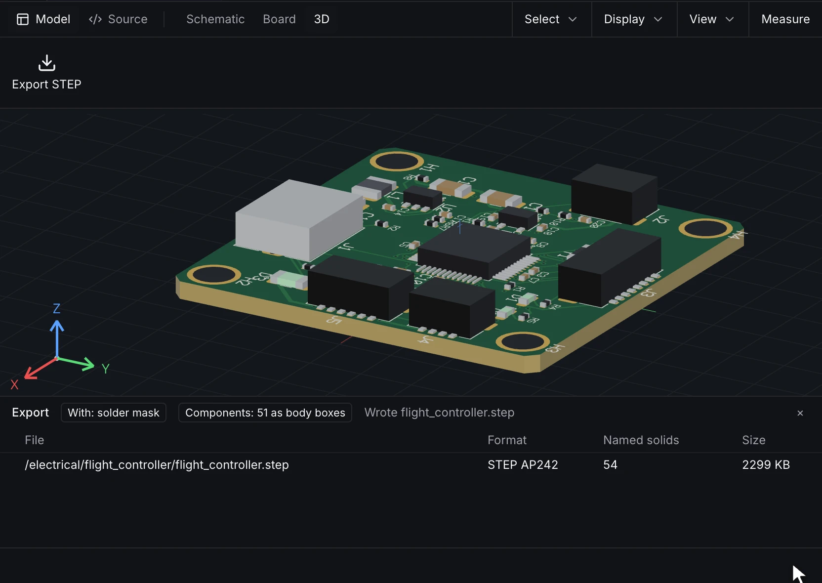
- STEP of the assembled board
Familiar shortcuts and standards compliant
Shortcuts you know
Pick the KiCad or Altium Designer keymap in Settings, and the wiring, placement and routing shortcuts match the ones you use now.
Libraries
KiCad symbol and footprint libraries open as RunMat libraries, and Altium libraries import with the project. Symbols, footprints and orderable parts stay separate.
Rules
KiCad net classes and custom rules, and Altium design rules, become RunMat rules by class, by net or for one net, applied in a stated order.
Manufacturing standards
Gerber X2, ODB++, IPC-2581 and IPC-D-356A go to the same board houses, and KiCad export stays available for partners who work from KiCad files.
Use RunMat with Claude Code, Codex or its built-in agent
Connect Claude Code, Codex or another AI agent through MCP, or use RunMat's built-in agent, a harness built for engineering work. The RunMat Agent guides you through a design: it asks where a rail such as +5V comes from and which room a repeated channel should copy, runs ERC and DRC and fixes what they find, and launches board studies.
Every change comes back staged as a diff of the schematic or the layout, with the affected parts selected on the board, to keep or undo one change at a time. Approval gates decide which changes to copper, rules, placement and interfaces need a sign-off, and locked copper stays as it is. The agent works with virtually any base model, including OpenAI's and Anthropic's.


Start designing boards in RunMat
Download the desktop app, or open RunMat in your browser and start from an example.
How does RunMat work?
Every RunMat circuit is a text file, and the board layout is a second file beside it. The schematic editor and the agent both edit these files.
A circuit works like code. A sheet is a module that other sheets place and repeat, parts come from shared library files, and each change is a diff to review and merge in Git. An AI model can read and edit a circuit as reliably as it edits code.
Design languageCircuit and layout filesSimulation study files
circuit lowpass {root = mainsheet main {port IN : inport OUT : outcomponent R1 = { part = "R0402-10K" }component C1 = { part = "C0402-100N" }net GND = { global = true, power_flag = true }connect = [port.IN, net.IN, "R1.1"]connect = [port.OUT, net.OUT, "R1.2", "C1.1"]connect = [net.GND, "C1.2"]}// Check the corner frequency: the -3 dB bandwidth at OUTsimulation corner {sheet = mainsource VIN = { p = net.IN, ac = 1 V }analysis response = ac {from = 1 Hz,to = 100 kHz,points = 100}probe = [net.IN, net.OUT]measure f3db = {of = response,bandwidth = net.OUT,spec = { min = 150 Hz, max = 170 Hz }}}}
FAQ
01Can I bring designs from KiCad, Altium or EAGLE?
Yes. KiCad 9 and 10 projects open with hierarchy, symbols, footprints, net classes, custom rules, stackup, tracks and zones, and save back as KiCad with the same netlist, rules and copper; RunMat lists any item it did not carry. Altium Designer, EAGLE and EasyEDA projects import with their schematics, boards and libraries.
02Does it have hierarchical schematics?
Yes. Sheets nest, a sheet can repeat as channels bound to buses, and one channel's placement and routing copy to the others.
03How many layers can a board have?
RunMat ECAD sets no fixed copper-layer limit. Stackups use through, blind, buried and micro vias. KiCad export writes boards up to KiCad's limit of 32 copper layers.
04Which fabrication files does it write?
Gerber X2, ODB++, IPC-2581, NC drill, pick-and-place, BOM, assembly and fabrication drawings, and STEP for the mechanical model.
05Which SPICE analyses are supported?
Operating point, DC sweeps, AC frequency response and noise, and transient, plus parameter sweeps and Monte Carlo over component tolerances. Library parts carry SPICE models, and models in SPICE3, PSpice or LTspice syntax can be added to any part.
06Is RunMat ECAD free PCB design software?
RunMat ECAD is free in production for individuals, including freelancers; students and faculty at an academic institution, for teaching or research there; contributors to an open-source project, for work on that project; and organizations with 250 or fewer people and US$10M or less in annual revenue. Anyone can evaluate it under the evaluation terms in the RunMat license. Production use at larger organizations needs a Professional seat. Free and Professional include the same ECAD features, and simulations use the plan's weekly physics simulation allowance.
07Does it work offline?
Yes. The desktop app edits, checks, exports and runs simulations on your computer with no internet connection. A network connection may be required for security and permission checks. The browser app runs the same editor.
08Can a team self-host RunMat ECAD?
Enterprise covers self-hosted RunMat servers, including air-gapped networks, with SSO, SAML and SCIM and audit controls. On Free and Professional, projects live on each person's computer or in RunMat cloud projects.
09Can checks run in CI?
Yes. runmat test runs ERC, DRC, review checks and circuit simulations on each commit and fails the build on an error.