
Predict magnetic flux, current density and losses in electrical parts
Check that a core stays below saturation at rated current, and that its conductors and insulation stay within their limits. Import the STEP file, write the materials, terminals and surrounding air in a short text file, and RunMat solves it.
RunMat works with you to set up your studies
Go from a CAD file to a complete, runnable study in minutes.
RunMat asks you guided questions to set up the study. It checks for missing terminals, potential references, the far field and the rest of the simulation setup, so the study is ready before you run it.
You own the study file: run it, review it and check it into version control. Model anything from the resistance of a single busbar to an induction coil heating a gear with multiphysics.
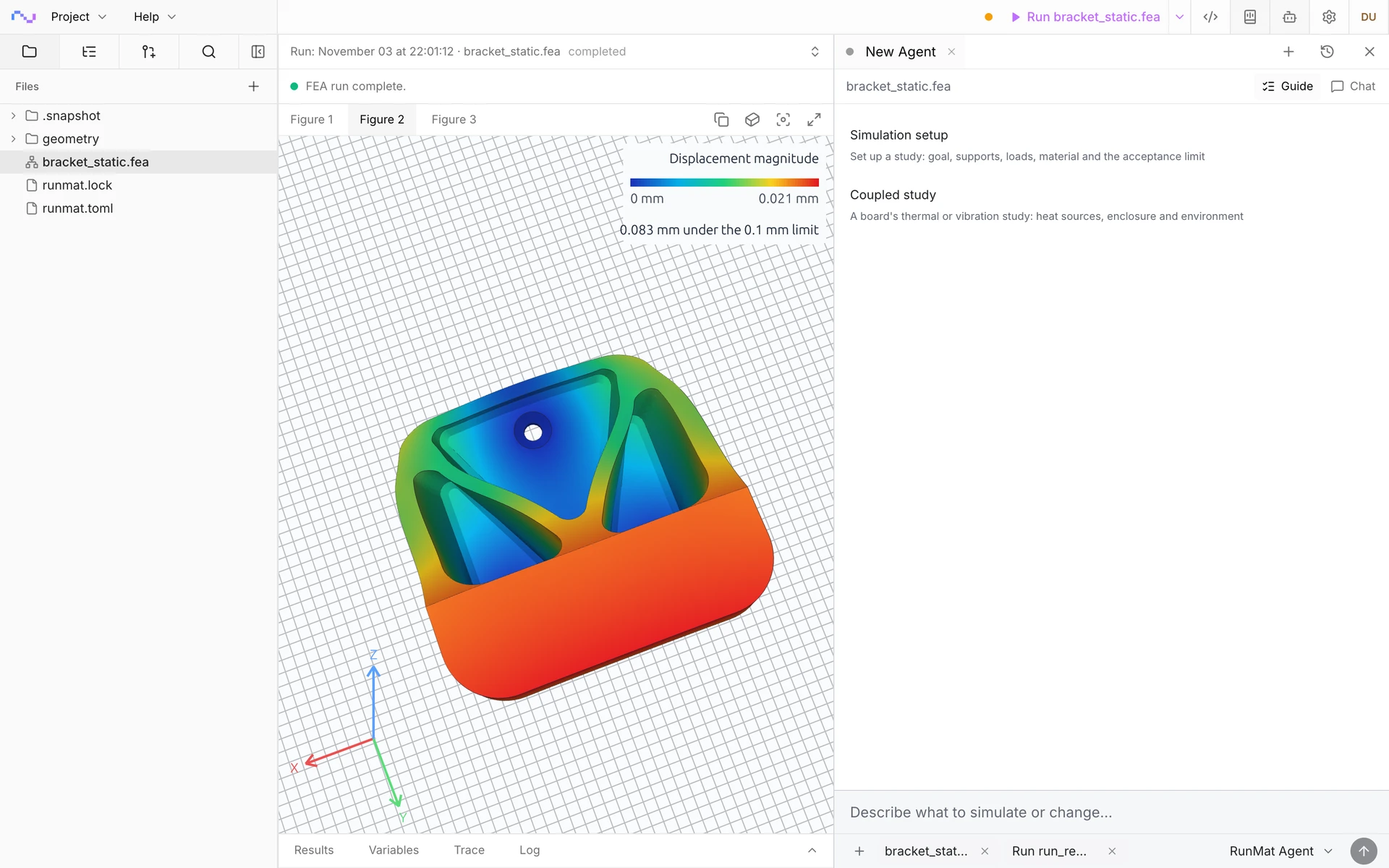


Run a simulation across your machines
The same study runs on every core of one computer, or spreads across several machines when the model is large or there are many cases to solve. On Professional, each person's three computers run together as a cluster, and larger clusters run under Enterprise.
RunMat helps you answer electrical questions before you build the hardware
Does the core stay out of saturation?
Get the flux density in every limb of a core and across its gap at rated and peak current, and check the peak against the material's saturation flux density.
Where does current crowd?
See current concentrate around bolt holes, bends and joints, and get the voltage drop and resistive loss of the whole conductor at its rated current.
Will the insulation hold?
Find the peak electric field around electrodes and in the insulation, and check it against the design stress, such as 4 kV/mm in cast epoxy, at the location where it governs.
How much power goes into the part at each frequency?
Solve skin and proximity effect at every drive frequency, and get the AC resistance, the loss in each body and the temperature that loss causes.
The following electromagnetic simulation types are supported
Steady current flow
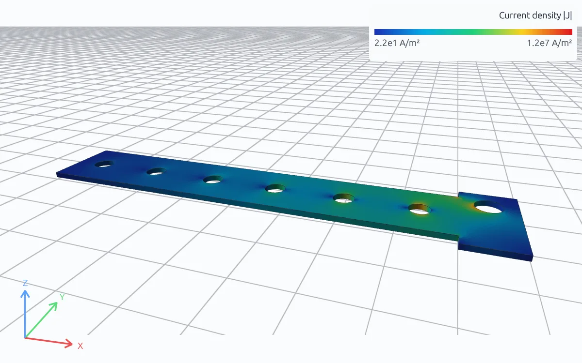
Potential and current density in conductors under an applied voltage or current, for resistance, current crowding and resistive loss. In the busbar shown, 300 A from six cells crowds to 10.0 A/mm² beside the last cell bolt, and the drop from the first cell bolt to the tab is 8.8 mV.
Electrostatics
Field strength and stored energy in insulation and around electrodes, with fixed or floating conductors, such as a high-voltage electrode cast in epoxy checked against 4 kV/mm with a sharp edge and with a rounded one.
Magnetostatics
Magnetic field from steady currents through cores, gaps and the surrounding air, such as the gap flux density of a current sensor at its rated current.
Time-harmonic
Fields and induced currents at one or more frequencies, with skin and proximity effect solved in the conductors, for AC resistance, eddy-current loss and induction heating. The loss heats a steady or transient thermal analysis of the same parts.
Transient
Eddy currents and fields over time from switching edges, pulses and fault currents, stepped from rest or an initial state.
Saturating iron
Cores driven toward saturation, with permeability from the material's B–H curve, for the gap flux a core loses at peak current.
Model sources, boundaries and materials
Define the terminals, sources, references and materials of complex cases.
Sources
- Terminal voltage, constant or as a signal
- Total current through a terminal
- Current density on a face
- Impressed current density through a coil or conductor body
- Charge on a face and charge density in a volume
- Frequency and time signals for AC and pulsed drive
Boundaries and references
- Fixed potential, ground and potential reference
- Equipotential terminals and floating conductors
- Integral current constraints
- Far field and perfectly conducting walls
- Magnetic insulation and Coulomb gauge
Materials
- Electrical conductivity and its temperature coefficient
- Relative permittivity
- Relative permeability, constant or from a saturating B–H curve
- Thermal properties for the heat the loss causes
Results
- Potential, electric field and displacement
- Current density and Joule loss
- Flux density and field intensity
- Terminal voltage, current and complex power per frequency
- Joule power checked against terminal power on every solve
RunMat can be used directly by Claude Code, Codex and other MCP clients
Connect RunMat to Claude Code, Codex or another MCP client, and the AI tool you already use sets up and runs the same studies from your CAD file. Its agent writes and edits the .fea study, RunMat checks and solves it, and the results come back to the agent and appear in RunMat Desktop.
FAQ
01Which electromagnetic problems is RunMat built for?
Fields and currents in and around parts from DC to power and switching frequencies: current sensors, coils and cores, busbars and connectors, induction heating, eddy-current loss, electrodes and insulation. The fields, the currents and the heat they cause are solved on the parts from CAD, with the air around them.
02Do I need to model the air?
For magnetic and AC fields, yes. The air is its own body in the CAD file around the parts, such as the air around the sensor's core and primary, and its outer faces are the far field. For current flow inside a conductor or the field inside insulation, the parts alone are enough.
03Can the loss heat the part?
Yes. The loss from a current-flow or time-harmonic analysis becomes the heat source of a steady or transient thermal analysis on the same mesh, with the total heat equal to the electrical loss, as in induction hardening.
04How do I get the resistance of a part?
Apply a voltage between two terminals in a steady current flow analysis and read the terminal current, or apply a current and read the voltage. Resistance is their ratio. A time-harmonic analysis reports the terminal impedance at each frequency, which gives the AC resistance with skin effect included.
05How fine does the mesh need to be for AC loss?
Fine enough to resolve the skin depth δ = √(2/(ωμσ)) with several elements where the loss matters. In copper at 50 Hz δ is about 9.3 mm, and at 10 kHz it is about 0.66 mm. Compare two mesh sizes on the loss you report.
06Why does my static field fail to solve?
A potential needs a reference: at least one fixed potential on each connected conductor. A magnetostatic study needs a grounded far field, including the ends of a conductor whose current leaves the model, and one Coulomb gauge. RunMat reports the missing reference instead of adding one.
07Can an AI model write an electromagnetic study?
Yes. A study is plain text with units on every value, so an AI coding agent such as Claude Code or Codex can write it from a description of the parts, the terminals and the drive, and runmat check reports any mistake with its line, such as a current written as a current density, before anything is meshed.