
Evaluate
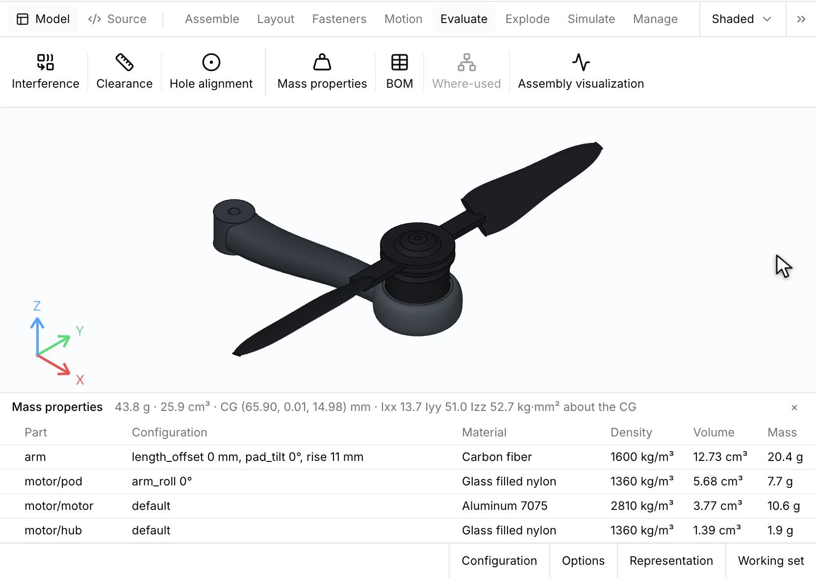
Evaluate measures a part or an assembly in its active configuration. The Desktop lists each result under the canvas; the agent reads the same results through design.inspect, and checks can gate on them.
| Command | Works on | Result |
|---|---|---|
evaluate.mass-properties | a part or an assembly | mass, center of gravity and inertia about it |
evaluate.interference | an assembly | pairs of occurrences whose solids overlap, with the overlap volume |
evaluate.clearance | an assembly | pairs closer than a gap you set |
weldment.cut-list | a weldment part | its structural members, grouped |
evaluate.draft | a part | each face's draft angle for a pull direction, in bands, with the model colored by band |
simulate.check | a part or an assembly | the study checks: densities, overlaps and open contacts, before a study meshes |
Mass properties
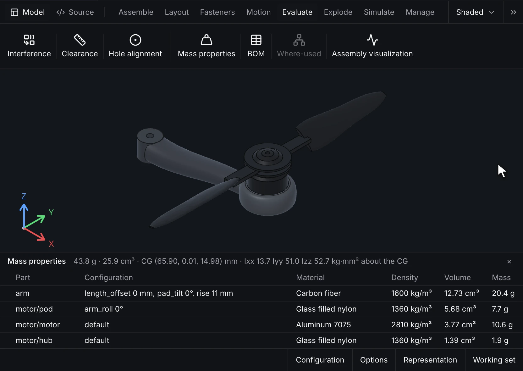
A part weighs its output bodies at their density: the output's density property when it has one, else its material's density from a table of common alloys, plastics and composites matched by the words in the material's name (material.aluminum_7075, steel_300m, carbon_prepreg, nylon, fr4). An assembly adds every placed part occurrence at its world placement: its center of gravity is mass-weighted, and its inertia is taken about that center by the parallel-axis theorem,
where and are each occurrence's mass and inertia about its own center, is the offset of that center from the assembly's, and is the identity. The result lists parts with no density, so a missing material never hides as a light assembly.
Draft analysis
Draft analysis takes a pull direction (an origin plane or axis, or a picked face) and a minimum draft angle, 1° by default, and sorts every face by its angle to the pull:
| Band | Color | Meaning |
|---|---|---|
| Positive | green | drafts toward the pull by at least the minimum |
| Negative | blue | drafts away from the pull by at least the minimum, so it releases from the other mold half |
| Needs draft | red | some of the face is within the minimum of parallel to the pull; a warning |
| Straddles | amber | crosses the parting line, so part of the face drafts each way |
The canvas colors each face by its band, with a legend of the face counts, and the result's rows name each face.
Interference and clearance
Interference finds pairs of occurrences whose solids share volume. Clearance finds pairs whose surfaces come closer than a gap, such as 0.5 mm between moving parts. Each pair names both occurrences by path (arm_front_left/motor), so a pick in the result selects them in the canvas.
A check after a change can be limited to the occurrences the change added or moved: design.inspect with the interference section and changed (occurrence names or paths, * globs) checks only the pairs those occurrences are in. The answer lists the overlaps the change brings and leaves out overlaps the assembly already had between other parts, such as a screw modelled at its nominal size in a tapped hole. Bodies and pair results are kept between checks, so a second check after a small fix regenerates only the parts the fix changed.
{ "path": "/drone.assembly", "sections": ["interference"], "changed": ["skid_*", "tube_*"] }Study checks
A study that names a part or an assembly checks the design before it meshes, and the Desktop runs the same checks on demand:
- Mass: every part occurrence has a density, from its
densityproperty or its material, so the study can assign its material and its loads from gravity and acceleration are right. A part with no density is an error. - Fit: no two occurrences share material, since an overlap meshes as one region with doubled stiffness and mass. An overlap is an error.
- Contacts: pairs closer than the contact gap (0.1 mm by default) that don't touch are warnings, since a bonded or contact pair that never meets carries no load until the gap closes. Pairs that touch, with a gap of 1 µm or less, are listed as contacts for information.
The summary reads ready to mesh with the count of warnings, or the count of errors to fix first.
Cut lists
A weldment's cut list groups identical structural members: item, quantity, profile, material, cut length, start and end angles, and mass each. The same list can be placed on a drawing as a cut_list table; see Drawing views and annotations.
Design for manufacture
A part's manufacturing features (bodies, holes, pockets, fillets, sheets, flanges and ribs, each with measured attributes) are checked by rule packs for machining, sheet metal, molding and additive: hole depth over diameter, edge distance, sharp internal corners in pockets, bend radius over thickness, wall thickness, draft and undercuts. A company pack can tighten or extend the rules. A failed check is a cad.dfm.check_failed diagnostic on the feature.
Surface and shape analysis
Section properties, wall-thickness maps, undercut maps for a pull direction, curvature and zebra stripes, and deviation from a reference body, each coloring the model as draft analysis does Not yet releasedStatus.