
Features
A part's geometry is its feature history: feature <name> = <operation>(…) statements, regenerated in the order they are written. Each feature names its inputs (sketches, faces, bodies) by reference, and later features name what it made: feature.body.face.end, feature.bolt.face.wall(a). Every feature takes suppressed to leave it out of the history.
Solids from sketches
| Operation | Makes | Main parameters |
|---|---|---|
extrude | a prism from a closed profile | profile; an extent: distance, through_all, up_to_next, up_to, extent = offset_from_face(face, offset); symmetric, reverse, second = blind(distance); thin = { thickness }; mode |
revolve | a solid of revolution | profile, axis, angle, mode |
sweep | a profile along a path | profile, path, follow_path, mode |
loft | a solid through profiles in order | profiles, mode |
rib | a rib from an open sketch | profile, thickness, depth, reverse |
emboss | raised or recessed text or shapes on a face | profile, face, height |
mode is new (the default for the first solid), add, cut or intersect. A part with a plate and a cut pocket:
runmat 0.7
std 1

part pocket_plate {
    sketch outline on origin.xy {
        l1 = line(start = [0 mm, 0 mm], end = [80 mm, 0 mm])
        l2 = line(start = [80 mm, 0 mm], end = [80 mm, 50 mm])
        l3 = line(start = [80 mm, 50 mm], end = [0 mm, 50 mm])
        l4 = line(start = [0 mm, 50 mm], end = [0 mm, 0 mm])
    }
    feature body = extrude(profile = sketch.outline, distance = 12 mm)
    sketch pocket_s on feature.body.face.end {
        p1 = line(start = [20 mm, 15 mm], end = [60 mm, 15 mm])
        p2 = line(start = [60 mm, 15 mm], end = [60 mm, 35 mm])
        p3 = line(start = [60 mm, 35 mm], end = [20 mm, 35 mm])
        p4 = line(start = [20 mm, 35 mm], end = [20 mm, 15 mm])
    }
    feature pocket = extrude(profile = sketch.pocket_s, distance = 5 mm, reverse, mode = cut)
    output pocket_plate = { body = feature.body.body }
}
The revolved forms:
feature spin = revolve(profile = sketch.s_rev, axis = origin.z, angle = 360 deg)
feature groove = revolve(profile = sketch.s_gr, axis = axis.gaxis, angle = 360 deg, mode = cut)
feature sw = sweep(profile = sketch.s_swp, path = sketch.s_path)
feature lf = loft(profiles = [sketch.s_l0, sketch.s_l1, sketch.s_l2])
feature box = extrude(profile = sketch.s, distance = 10 mm, thin = { thickness = 2 mm })
feature post = extrude(profile = sketch.s2, extent = offset_from_face(face = feature.body.face.end, offset = 2 mm))
feature logo = emboss(profile = sketch.s_logo, face = feature.body.face.end, height = 1 mm)
In the Desktop, Revolve takes the sketch as its profile, and the axis can be a straight edge picked on the model. The preview turns the profile through the angle, here a full turn that makes two hinge knuckles on a leaf's edge:
A sweep keeps the profile parallel to itself by default: the profile is translated along the path, so every path segment must leave the profile's plane. With follow_path, the profile keeps its angle to the path instead. It turns through each arc of the path and is mitred where two straight segments meet, so the path can bend into the profile's own plane. Pipe, duct and cable runs use it:
feature run = sweep(profile = sketch.pipe_s, path = sketch.run_s, follow_path)A follow_path sweep needs a closed profile and the exact geometry engine; the grid test kernel builds it only along a straight path.
Holes and threads
hole drills one hole at each key of at, on a planar face. Each hole's faces are keyed: feature.mount.face.wall(a).
| Parameter | Meaning |
|---|---|
face | The face the holes start on. |
at | Keyed positions: { a = point(15 mm, 25 mm, 10 mm), b = sketch.marks.p1.at }. |
diameter, depth or through_all | Size and extent. |
form | counterbore(diameter, depth), countersink(diameter, angle), slot(length), pipe_tap. |
spec | A standard size: { standard = iso, size = M6 }, { standard = npt, size = "1/8" }. The size sets the diameters. |
series | The hole's other end in a stack: { end = { hole = tapped, modelled = true } }. |
feature cb = hole(face = feature.body.face.end, at = { c = point(40 mm, 25 mm, 10 mm) }, through_all, form = counterbore, spec = { standard = iso, size = M6 })
feature cs = hole(face = feature.body.face.end, at = { a = point(60 mm, 25 mm, 10 mm) }, diameter = 6 mm, depth = 8 mm, form = countersink(diameter = 12 mm, angle = 90 deg))
feature slot = hole(face = feature.body.face.end, at = { s = point(40 mm, 25 mm, 10 mm) }, diameter = 6 mm, through_all, form = slot(length = 20 mm))
feature m6_thread = thread(face = feature.tap.face.wall(m6), spec = { designation = M6x1, pitch = 1 mm, depth = 0.54 mm, class = "6H" })
Edges and faces
| Operation | Does | Main parameters |
|---|---|---|
fillet | rounds edges | edges, radius |
chamfer | bevels edges or vertices | edges; distance, distance and angle, or distances for a vertex; flip |
face_fillet | blends between two face sets | first, second, radius |
full_round | rounds a face away between two side faces | first, center, second |
shell | hollows a body | body, thickness, open_faces, outward |
draft | tilts faces for molding | faces, neutral, angle |
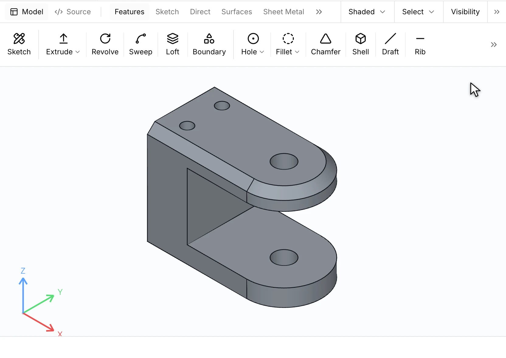
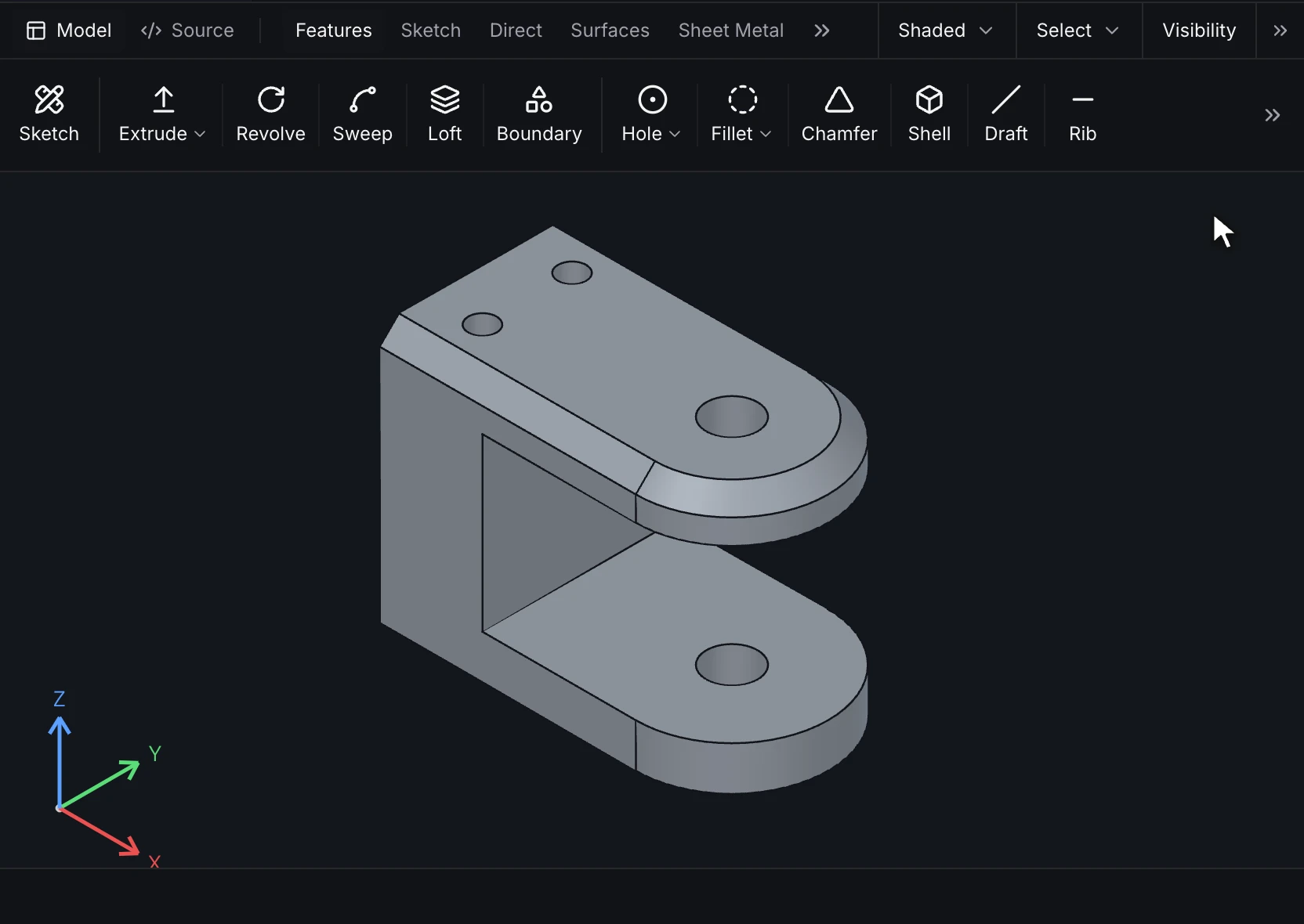
In the Desktop, Fillet takes the edges you pick on the model and previews the rounds. Type the radius in the box on the model or in the form, then confirm:
Chamfer works the same way: pick the edges, then set the distance on the model. A fillet or chamfer carries on along the edges tangent to the picked one, so the bevel below follows the lug around its rounded end:
This tray drafts its walls 2° and shells itself open at the top, then adds a post and mirrors it about a datum plane:
runmat 0.7
std 1

part tray {
    sketch s on origin.xy {
        l1 = line(start = [0 mm, 0 mm], end = [100 mm, 0 mm])
        l2 = line(start = [100 mm, 0 mm], end = [100 mm, 60 mm])
        l3 = line(start = [100 mm, 60 mm], end = [0 mm, 60 mm])
        l4 = line(start = [0 mm, 60 mm], end = [0 mm, 0 mm])
    }
    feature body = extrude(profile = sketch.s, distance = 25 mm)
    feature walls = draft(
        faces = [feature.body.face.side(s.l1), feature.body.face.side(s.l2), feature.body.face.side(s.l3), feature.body.face.side(s.l4)],
        neutral = origin.xy,
        angle = 2 deg
    )
    feature hollow = shell(body = feature.body.body, open_faces = [feature.body.face.end], thickness = 2 mm)
    feature mid = plane.offset(base = origin.yz, distance = 50 mm)
    sketch boss on origin.xy {
        c = circle(center = [20 mm, 30 mm], radius = 4 mm)
    }
    feature post = extrude(profile = sketch.boss, distance = 20 mm, mode = add)
    feature twin = mirror(features = [post], plane = plane.mid)
    output tray = { body = feature.body.body }
}
Patterns and mirrors
pattern repeats features (features = […]) or bodies (bodies = […]); mirror reflects features about a plane. Each copy is keyed, so a later feature can name one copy's faces.
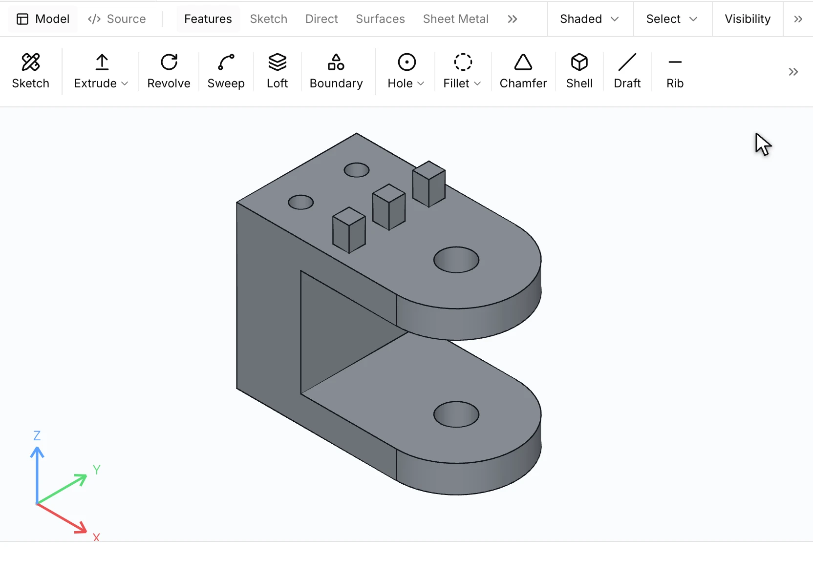
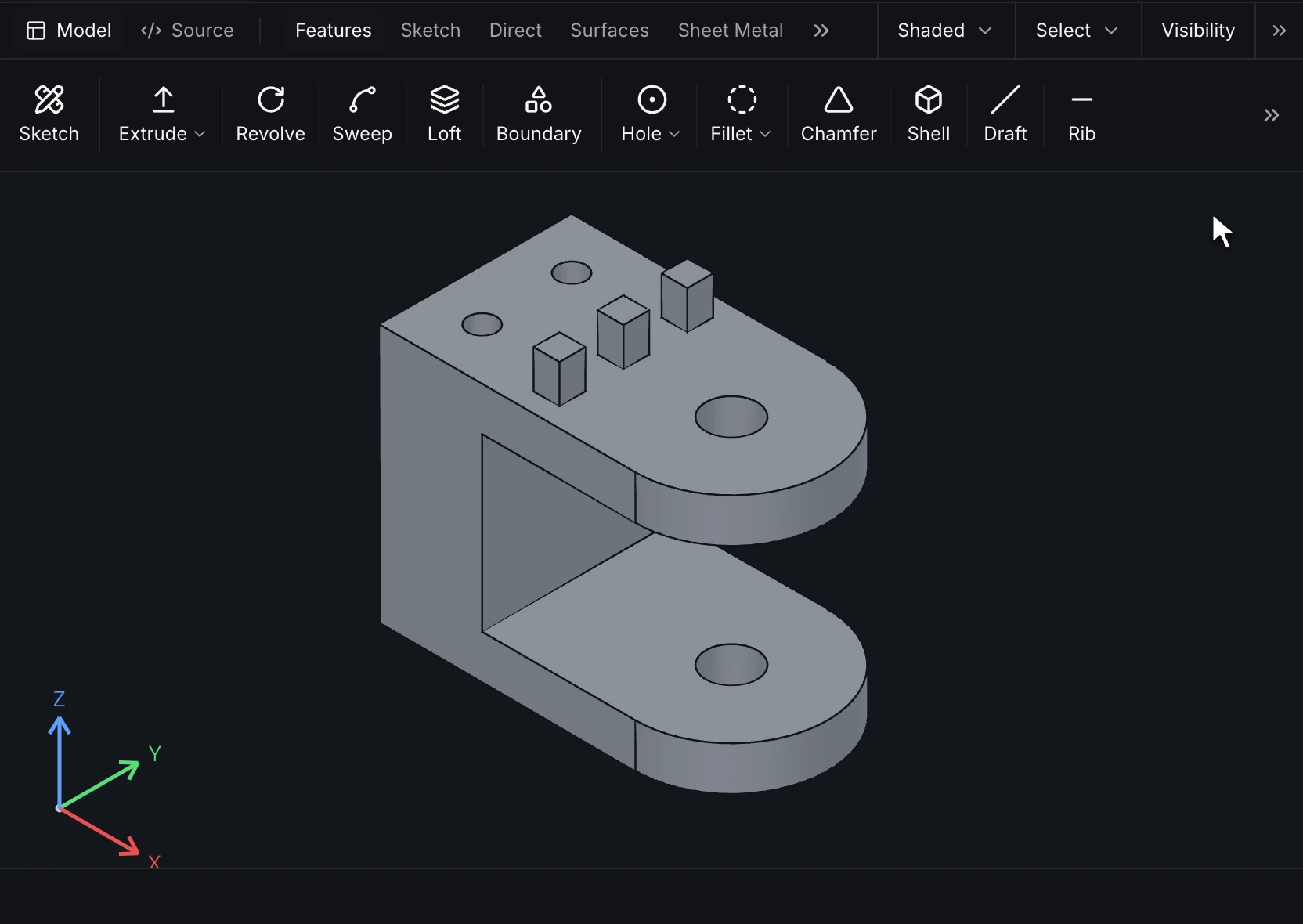
In the Desktop, select the feature to repeat, start Pattern and pick an edge for the direction. The copies preview along it; set the spacing and confirm:
| Layout | Parameters |
|---|---|
linear(direction, spacing, count) | count copies in all, spacing apart |
grid(first, first_spacing, first_count, second, second_spacing, second_count) | a two-way array |
circular(axis, count, angle) | count copies equally spaced over angle |
sketch(sketch) | one copy at each point of a sketch |
curve(curve, count, spacing) | copies along an edge or curve |
fill(boundary, spacing, margin, seed) | copies filling a sketch region |
table(rows) | one copy per row of offsets { key, dx, dy, dz } |
skip = [{ instance = linear, step = 2 }] leaves copies out.
feature row = pattern(features = [h], layout = linear(direction = origin.x, spacing = 15 mm, count = 4), skip = [{ instance = linear, step = 2 }])
feature ring = pattern(features = [pin], layout = circular(axis = axis.cax, count = 6, angle = 360 deg))
feature pat = pattern(features = [pocket], layout = sketch(sketch = pts))
feature copies = pattern(bodies = [feature.body.body], layout = table(rows = [{ key = aft, dx = 0 mm, dy = 100 mm, dz = 0 mm }]))
feature mir = mirror(features = [pk2], plane = plane.mp)
Bodies
| Operation | Does |
|---|---|
boolean.union(target, tools), boolean.subtract(…), boolean.intersect(…) | combines bodies; keep_tools keeps the tool bodies |
split(body, tool) | splits a body with a plane or surface; the pieces are body(side = positive) and body(side = negative) |
body_op.delete(bodies), body_op.translate(bodies, dx, dy, dz) | removes or moves bodies |
import(source, digest) | a body from a STEP file, held by the file's digest; its named faces read as feature.step.face("Top") |
library(def, args, mode) | an instance of a reusable feature definition (feature_def) |
feature join = boolean.union(target = feature.body.body, tools = [feature.ear.body])
feature halve = split(body = feature.body.body, tool = plane.cutp)
feature drop = body_op.delete(bodies = [feature.halve.body.body(side = negative)])
feature step = import(source = "supplier/housing.step", digest = d2)
feature boss1 = library(def = "feature_def.boss", args = { h = 8 mm }, mode = add)
Datums and curves
| Operation | Makes |
|---|---|
plane.offset(base, distance), plane.angle(base, axis, angle), plane.three_point(a, b, c), plane.mid(a, b), plane.normal_to_curve, plane.tangent_to_face(face, at) | a datum plane, read as plane.<name> |
axis.through(a, b), axis.of_face, axis.of_edge, axis.two_planes, axis.normal | a datum axis, read as axis.<name> |
point.at, point.offset, point.center_of, point.on_curve, point.intersection | a datum point |
curve.helix(axis, start, pitch, turns), curve.spiral, curve.projected, curve.composite, curve.split_line, curve.intersection, curve.through_points, curve.equation | a 3D curve |
mate_connector(placement, offset) | a frame an assembly mates to |
feature mid = plane.offset(base = origin.yz, distance = 40 mm)
feature mp = plane.angle(base = origin.yz, axis = origin.z, angle = -45 deg)
feature tilted = plane.three_point(a = point(0 mm, 0 mm, 0 mm), b = point(10 mm, 0 mm, 0 mm), c = point(0 mm, 10 mm, 10 mm))
feature cax = axis.through(a = point(40 mm, 25 mm, 0 mm), b = point(40 mm, 25 mm, 10 mm))
feature coil = curve.helix(axis = origin.z, start = point(10 mm, 0 mm, 0 mm), pitch = 2 mm, turns = 3)
feature mc = mate_connector(placement = { on = frame, frame = { frame = on_face, face = feature.body.face.end } }, offset = [0 mm, 0 mm, 2 mm])
Surfaces
surface.extrude, surface.revolve, surface.sweep, surface.loft, surface.boundary, surface.fill, surface.planar, surface.ruled, surface.offset, surface.extend, surface.trim, surface.untrim, surface.knit, surface.thicken, surface.delete_hole, surface.cut_with_surface and surface.mid_surface build and edit sheet bodies; surface.thicken and surface.knit turn them into solids.
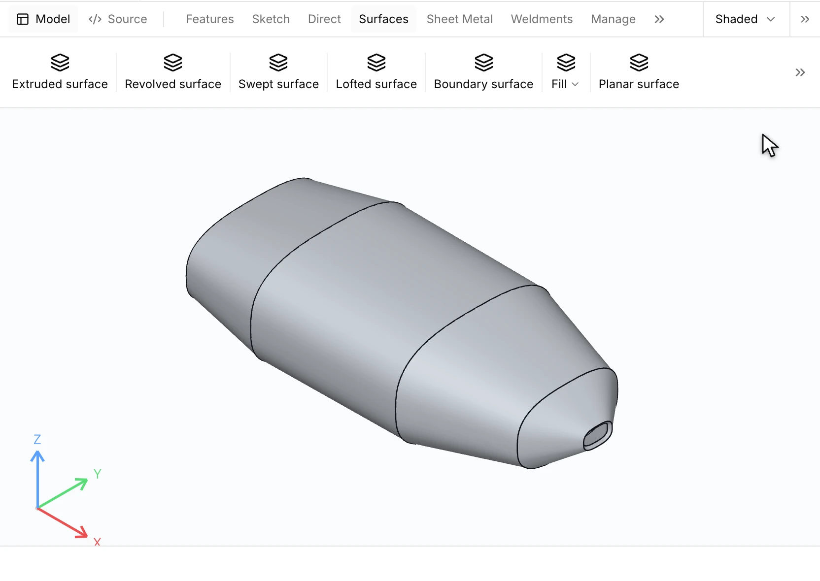
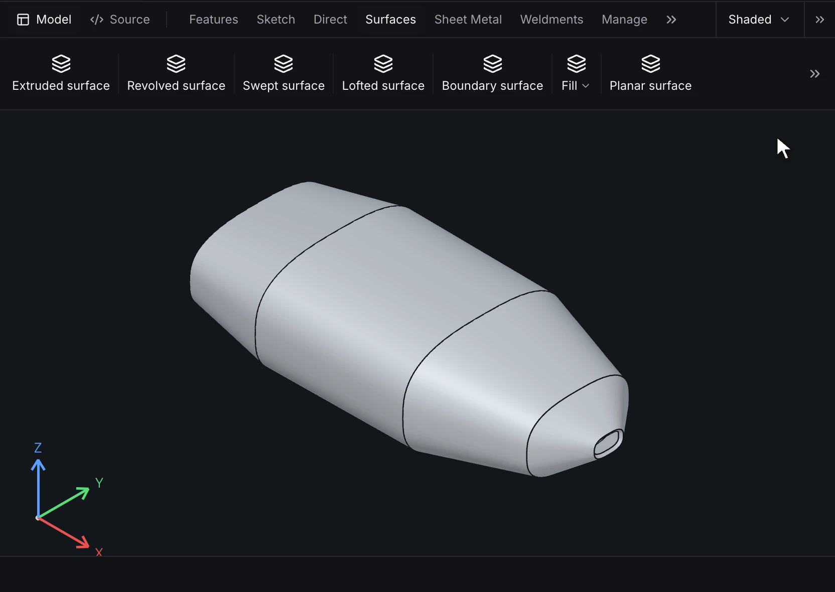
feature patch = surface.planar(profile = sketch.s)
feature grow = surface.extend(edges = [feature.patch.edge.boundary(s.b)], distance = 10 mm)
feature solid = surface.thicken(bodies = [feature.patch.body], thickness = 3 mm)
feature trim = surface.cut_with_surface(body = feature.body.body, surface = feature.sheet.body, keep = negative)
Sheet metal, weldments and molds
| Family | Operations |
|---|---|
| Sheet metal | sheet_metal.base_flange, edge_flange, miter_flange, hem, jog, sketched_bend, lofted_bend, convert_to_sheet_metal, closed_corner, break_corner, corner_relief, tab_and_slot, form_tool, unfold, fold, flat_pattern |
| Weldments | weldment.structural_member, trim_extend, end_cap, gusset, weld_bead |
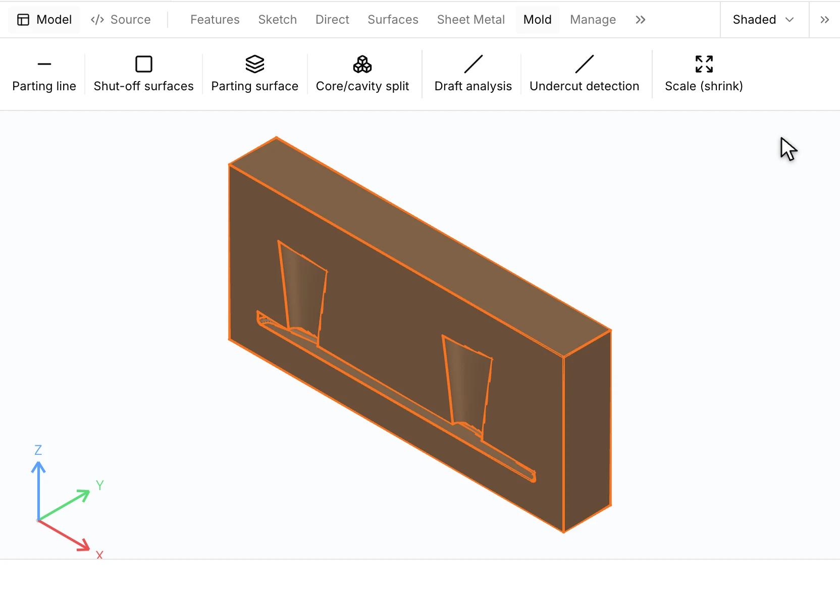
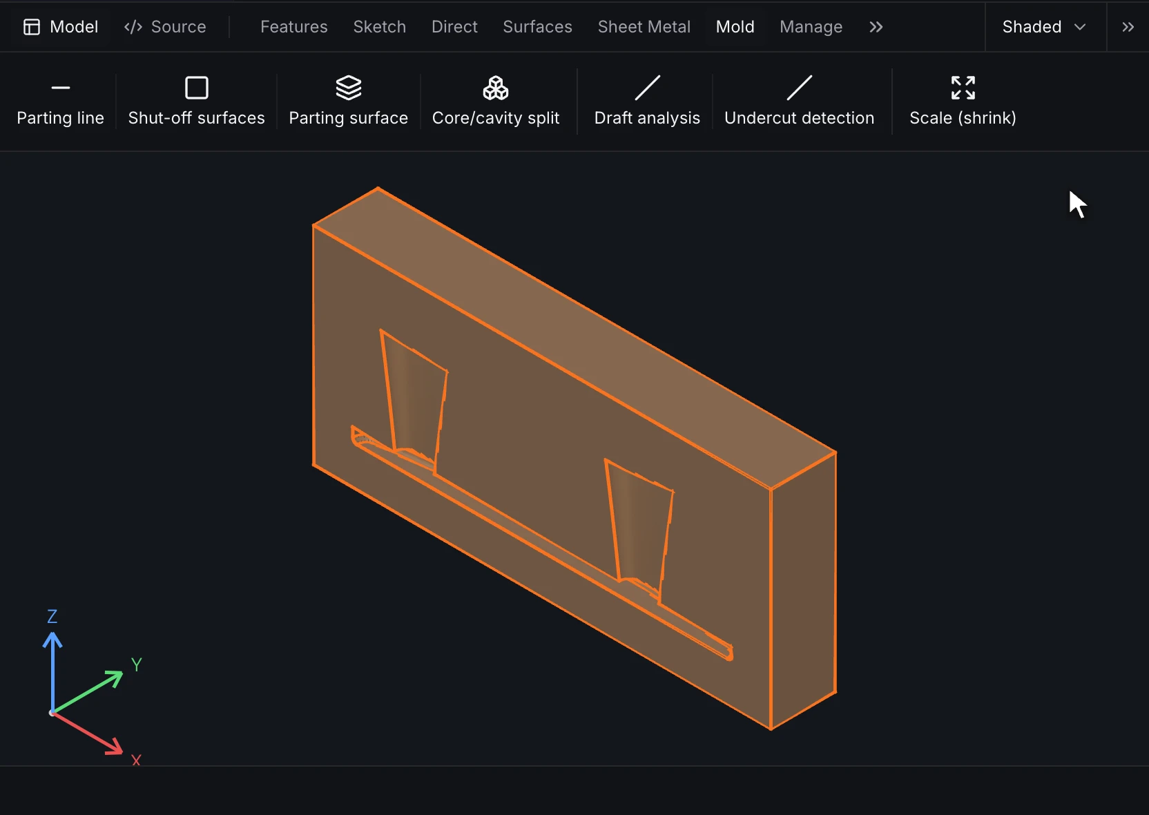
| Molds | mold.shrink, parting_line, shut_off, parting_surface, core_cavity, undercuts |
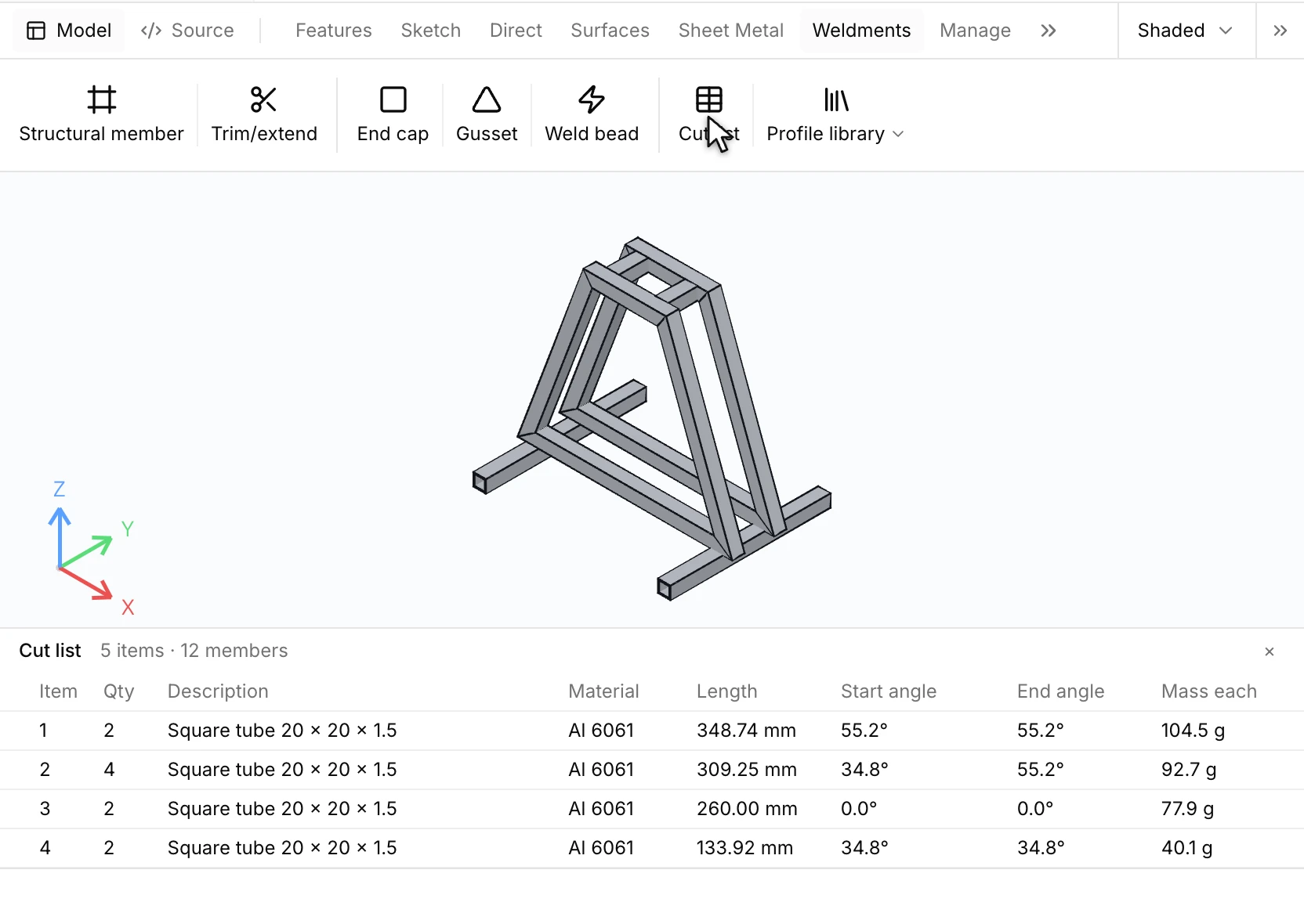
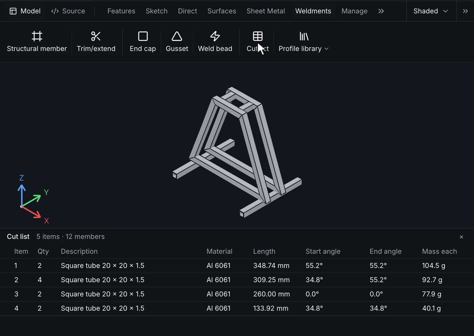
A sheet-metal part carries its rules (thickness, bend radius, K-factor) on its base flange, and flat_pattern unfolds it from a fixed face. A weldment's structural members follow the segments of a layout sketch with a profile and a material, and its cut list is a drawing table.
feature base = sheet_metal.base_flange(profile = sketch.s_chain, depth = 40 mm, rules = { thickness = 2 mm, bend_radius = 3 mm, rule = k_factor(k = 0.44) })
feature flat = sheet_metal.flat_pattern(fixed_face = feature.base.face.sheet(base, ordinal = 0))
feature members = weldment.structural_member(groups = [{ sketch = layout, segments = [bottom, right, top, left], profile = rect_tube(width = 0.02, height = 0.02, wall = 0.002), material = S235 }])
feature shrink = mold.shrink(bodies = [feature.body.body], x = 0.005, y = 0.005, z = 0.005)
feature draft_check = mold.parting_line(body = feature.body.body, pull = origin.z, min_draft = 1 deg)
Direct edits
direct.move_faces, direct.replace_faces, direct.delete_faces and direct.move_bodies edit imported or finished geometry as features in the history. keep lists relations the edit must keep, such as two faces staying parallel; an edit that would break one is an error (cad.direct.relation_broken).
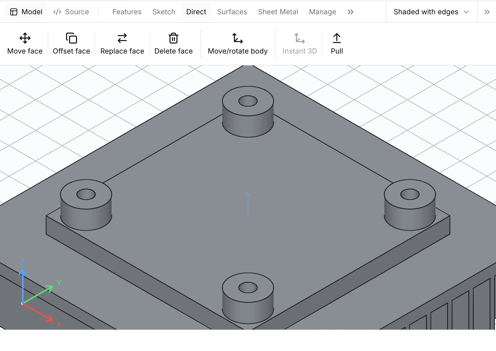
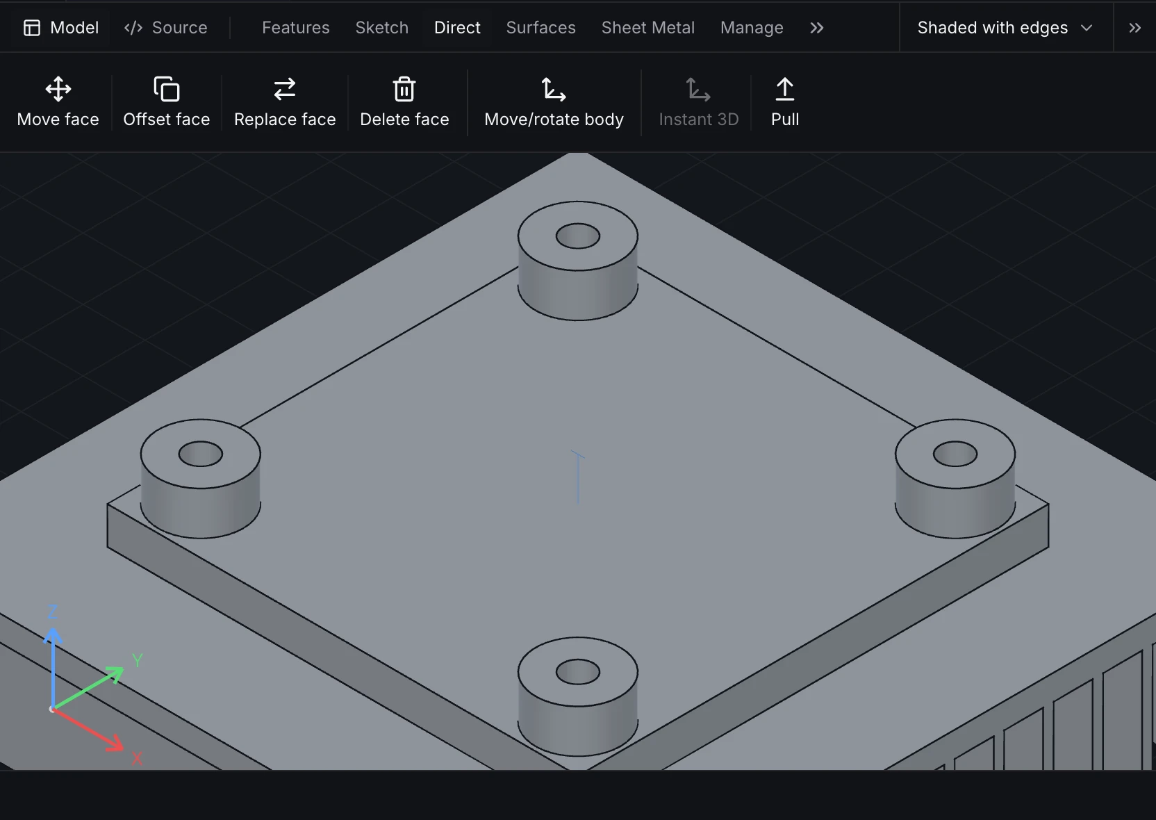
feature pull = direct.move_faces(faces = [feature.body.face.end], motion = offset(distance = 5 mm), keep = [{ keep = parallel, a = feature.body.face.end, b = feature.body.face.start }])