
Meshing
RunMat turns exact CAD geometry into a deterministic, solver-ready tetrahedral mesh. The resulting artifact contains nodes, tetrahedra, boundary topology, persistent regions, interfaces, contacts, field mappings, the resolved meshing request, and a canonical identity. A companion evidence artifact records each stage's checks and resource usage.
Meshing has three entry points:
| Goal | Entry point |
|---|---|
| Mesh as part of an analysis | Declare mesh <id> on geometry.<id> in typed .fea source and run runmat run study.fea |
| Generate canonical artifacts directly from a shell | runmat mesh part.step |
| Generate, inspect, and display a mesh in RunMat code | part = geometry.load(...); solverMesh = meshing.generate(part); mesh(solverMesh) |
All three produce the same artifact for the same geometry and settings.
Element types
| Element | Nodes | Use |
|---|---|---|
| Tet4 | 4 | Linear tetrahedron. Quick studies, coarse checks and large thermal models |
| Tet10 | 10 | Quadratic tetrahedron. Boundary midside nodes are placed on the exact CAD surface, so curved fillets, holes and arcs keep their shape. Use it for stress, modal and other accuracy-sensitive work |
Boundary faces are Tri3 for Tet4 meshes and Tri6 for Tet10 meshes. Beam and shell models use the same imported geometry with section, layup, and orientation properties declared in the model; the mesher itself generates volume tetrahedra.
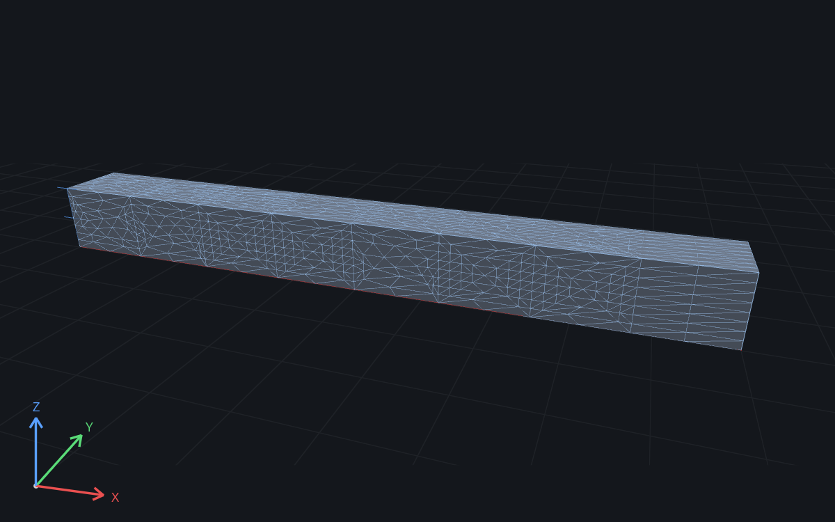
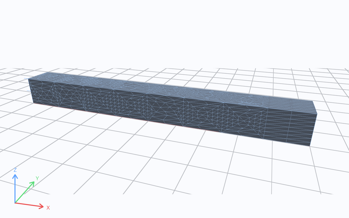
Solver mesh · m. Drag to rotate; scroll to zoom.
The view above is the saved quadratic mesh of the 1 m steel cantilever used in the mesh refinement guide, generated from its STEP file with a 175 mm target size, coarse on purpose so the guide can compare it with finer meshes.
The direct CLI and .fea paths import exact STEP, IGES, or Open CASCADE B-rep geometry. They
require a RunMat build with the native Open CASCADE (OCCT) capability. Official native CLI and
Desktop builds include it.
Quick start: mesh a study
Create bracket.fea beside a geometry directory containing bracket.step:
geometry bracket {
    file = "./geometry/bracket.step"
    units = mm
}

mesh bracket on geometry.bracket {
    tetrahedra {
        order = quadratic
        target_size = 5 mm
        maximum_deviation = 0.05 mm
        maximum_grading_ratio = 1.3
        deterministic_seed = 42
    }
}

material aluminum {
    mass_density = 2700 kg/m^3
    elastic {
        youngs_modulus = 68.9 GPa
        poisson_ratio = 0.33
    }
}

model bracket_model {
    assign material.aluminum to geometry.bracket.region.body
}

study bracket_static {
    geometry = geometry.bracket
    mesh = mesh.bracket
    model = model.bracket_model
    analysis static { structural static {} }
}
The geometry declaration admits exact CAD and gives its coordinates physical units. The mesh declaration says how to discretize that geometry. The study selects the mesh; material ownership is declared separately on the solid region. Check the complete source before running it:
runmat check bracket.fea
runmat plan bracket.fea
runmat run bracket.fea
check resolves modules, types, units, regions, and declaration contracts. plan reports the
selected geometry, mesh, model, execution policy, and logical work. run materializes the exact
geometry, generates or resolves the canonical solver mesh, compiles the model, and executes the
admitted analysis graph.
For a linear mesh, change only order = linear. Omit mesh settings when their
canonical defaults are acceptable; the geometry, mesh, and model bindings
remain required. The direct CLI and programmatic API expose a maximum-element admission cap; the
current .fea mesh declaration does not.
Mesh settings in a study
The typed .fea mesh declaration exposes the controls that are part of a study definition:
mesh bracket on geometry.bracket {
    tetrahedra {
        order = quadratic
        target_size = 5 mm
        maximum_deviation = 0.05 mm
        maximum_grading_ratio = 1.3
        deterministic_seed = 42
    }
}
Check and run it with:
runmat check studies/bracket_static.fea
runmat run studies/bracket_static.fea
The linear static guide shows a complete study with its procedure,
constraints, loads, and outputs. The declaration is resolved into the same canonical request used by direct generation. Algorithm
identities and implementation choices are recorded as evidence; they are not user-selectable
backends. maximum_grading_ratio limits how quickly the requested size may change through adjacent
regions. Lower values produce smoother transitions and can require more elements.
Every setting has a canonical default, taken from the mesher's request defaults. An omitted setting
takes its default, and a mesh declaration with no element block meshes the solid with linear
tetrahedra at those defaults:
| Setting | Default |
|---|---|
order | linear (shell triangles and beam lines are always linear) |
target_size | 10 mm |
maximum_deviation | 0.1 mm |
maximum_grading_ratio | 1.3 |
deterministic_seed | 0 |
cells_across_gap | 2 element layers |
An explicit setting still passes the usual type, unit, and value checks. A mesh declaration
accepts at most one tetrahedra, triangles, or lines block. cells_across_gap and refine
blocks are optional local controls, described next.
Local sizing controls
A tetrahedra block can refine named solid, face and edge regions, and can ask for a number of
element layers across thin gaps:
mesh bracket on geometry.bracket {
    tetrahedra {
        order = quadratic
        target_size = 5 mm
        maximum_deviation = 0.05 mm
        cells_across_gap = 3

        refine bolt_holes {
            on = geometry.bracket.region.hole_walls
            target_size = 1 mm
        }
        refine fillet_edges {
            on = geometry.bracket.region.fillet_edges
            target_size = 0.5 mm
        }
    }
}
refine <name> selects one named geometry region, the same regions constraints and loads select,
and requests a local target edge length on it:
| Region role | What the control sizes |
|---|---|
solid | Every cell of the solid, and the faces and edges that bound it |
face | The face triangles, the edges that bound the faces and the cells that touch them |
edge | The edge segments and the triangles and cells that touch the edges |
Away from a refined region, the size grows back to the global target_size no faster than
maximum_grading_ratio per element layer, so maximum_grading_ratio is the mesh's growth rate.
cells_across_gap = N asks for N elements through every thin gap and thin wall narrower than N
times the global target_size. Proximity sizing measures two kinds of gap:
- between two boundary edges that share no vertex, where the size across the gap is the gap divided by N, along the gap direction;
- between two faces that share no vertex and face each other across the gap: the two sides of a thin wall or plate, the inner and outer surfaces of a tube, or the two walls of a slot. Both faces get an isotropic size of the gap divided by N, so their triangles and every cell touching them resolve the gap with N elements, and the volume grades from there. The gap is measured between the faces' boundary samples whose separation lies within about 25 degrees of both surface normals, so faces that meet through a blend or a chamfer are not a gap.
Without cells_across_gap, edge proximity resolves two layers and faces are not measured, so a
mesh's identity and output stay the same as before the setting existed.
Precedence. Where controls meet, the smallest requested size wins. A face and the edges that
bound it, a solid and its faces, and the global size all constrain the shared mesh entities, and
the metric field combines them by most-restrictive intersection. The result is the same whatever
order the controls are written in, and a coarse control can't undo a finer one on a shared entity.
For this reason a local target_size must be smaller than the global target_size.
The checker rejects, with typed diagnostics:
| Code | Cause |
|---|---|
fea.semantic.mesh.control_region | on names a region of another geometry, an input, or a vertex or cell region. An unknown region name fails type checking |
fea.semantic.mesh.control_size | A target_size that is zero, negative, or not smaller than the global target_size |
fea.semantic.mesh.control_conflict | Two refine blocks on the same region, or two with the same name |
fea.semantic.mesh.control_setting | A setting other than on and target_size inside refine |
fea.semantic.mesh.cells_across_gap | A count outside 1 to 64 |
Every control is part of the canonical meshing request and its identity, so meshes with different controls have different identities. A mesh without controls keeps the identity it had before controls existed. When the geometry is materialized, each control's region resolves to persistent entities and becomes one metric contribution per entity in the same field that carries curvature, feature and proximity sizing.
Evidence. Each applied control adds one row per resolved entity to the meshing evidence's
sizing list, with the control name, the requested and resolved size, and the achieved corner
edge lengths (count, minimum, mean, maximum) on that entity: the boundary triangles of a face, the
boundary segments of an edge, or the cells of a solid.
Measured on the docs fixtures (linear tetrahedra):
| Case | Elements | Edge length on the controlled entity | Elsewhere |
|---|---|---|---|
Cantilever 1000 × 100 × 100 mm, target_size = 50 mm | 2,692 | end faces: mean 27.5 mm, max 45.5 mm | 257 to 299 cells per 100 mm of length |
Same, refine the loaded end to 12.5 mm | 5,178 | loaded end: 608 edges, mean 8.0 mm, max 12.5 mm | fixed end mean 19.8 mm; 2,560 cells in the last 100 mm, 277 to 331 in each other 100 mm |
Pipe r = 50 mm, L = 500 mm, target_size = 8 mm | 270,088 | inlet: mean 4.1 mm, max 7.9 mm | |
Same, refine the inlet to 2 mm | 325,854 | inlet: mean 1.3 mm, max 2.0 mm | outlet mean 3.9 mm, max 8.0 mm |
40 × 40 × 3 mm slab, target_size = 3 mm | 7,753 | 1.5 elements through the thickness | |
40 × 40 × 3 mm slab, target_size = 10 mm, cells_across_gap 2 / 3 / 5 | 35,659 / 90,471 / 263,933 | 2.7 / 3.7 / 5.6 elements through the thickness |
Elements through the thickness is the thickness divided by the mean edge length of the cells in the
middle half of the slab. Without cells_across_gap, the 10 mm slab fails volume quality
refinement.
The language does not currently expose boundary layers, hybrid element families, or user-selectable meshing algorithms.
Practical guidance
- Start with an explicit geometry unit and a target size based on the smallest feature that matters to the physics, not the model's overall bounding box.
- Set chordal deviation from acceptable boundary error. Curved surfaces often control mesh density even when the global target is larger.
- Use Tet10 for stress, bending and modal work, where linear tetrahedra are too stiff. Use Tet4 for temperature and quick checks.
- Keep a hard element ceiling in CI. Investigate a budget failure rather than accepting a mesh with reduced sizing or quality requirements.
- Save both CBOR artifacts and the JSON summary with analysis results. The mesh alone does not carry measured stage evidence.
- Use stable seeds and explicit settings for regression tests. Compare canonical digests only when geometry, request, and supported capability cohort are intended to match.
- Validate engineering conclusions with mesh-convergence studies: reduce target size and chordal deviation systematically and confirm that quantities of interest converge. The mesh refinement guide works through one on a cantilever.
A validated mesh proves that the discretization satisfies its declared geometric and numerical contracts. Engineering validation must also cover loads, constraints, material data, solver formulation, and mesh convergence. See Verification & Validation and Results & Trust for that workflow.
Generate a mesh from the command line
Given bracket.step, generate a linear tetrahedral mesh in meters:
runmat mesh bracket.step \
  --target-size 0.005 \
  --deviation 0.00005
This writes two files beside the source:
bracket.solver-mesh.cbor— the solver-ready mesh artifactbracket.meshing-evidence.cbor— independently bound stage and quality evidence
Use explicit destinations in scripts and CI:
mkdir -p artifacts
runmat mesh geometry/bracket.step \
  --output artifacts/bracket.mesh.cbor \
  --evidence artifacts/bracket.mesh-evidence.cbor \
  --target-size 0.005 \
  --deviation 0.00005 \
  --element-order tet10 \
  --max-elements 2000000 \
  --seed 42 \
  --json > artifacts/bracket.mesh-summary.json
Existing output files are protected. Pass --force only when replacing both outputs is intended.
RunMat stages the pair before publication, rolls back publication errors, decodes both outputs,
validates them, and verifies that the evidence and mesh identities agree before reporting success.
Example: mesh a tuning fork
The tuning-fork STEP file used in the modal examples declares millimeter units, so no
--source-units flag is needed. Sizes on the command line are in meters. This command requests
quadratic elements with a 4 mm target size and 0.2 mm chordal deviation:
runmat mesh tuning-fork.step \
  --target-size 0.004 \
  --deviation 0.0002 \
  --element-order tet10 \
  --seed 42
Solver mesh generated
mesh: tuning-fork.solver-mesh.cbor
evidence: tuning-fork.meshing-evidence.cbor
topology: 13068 nodes, 7057 tetrahedra, 3584 boundary facesRunning the same command again with the same file, settings, and seed writes a byte-identical solver mesh with the same canonical digest, so a mesh in a results archive can be regenerated and compared exactly.
Command-line options
runmat mesh --help is the command-line authority. Its principal controls are:
| Option | Meaning | Default |
|---|---|---|
--source-units meter|millimeter|inch | Coordinate units for sources that do not declare them | meter |
--target-size <meters> | Global target edge length used to construct the metric field | 0.01 |
--deviation <meters> | Maximum curve and surface chordal deviation | 0.0001 |
--element-order tet4|tet10 | Linear or quadratic tetrahedra | tet4 |
--max-elements <count> | Hard element ceiling | 10000000 |
--seed <integer> | Deterministic tie-breaking seed | 0 |
--output <path> | Solver mesh destination | Source name with .solver-mesh.cbor |
--evidence <path> | Evidence destination | Source name with .meshing-evidence.cbor |
--json | Print a machine-readable summary | Off |
--force | Atomically replace existing destinations | Off |
--cluster <id> | Execute through the named remote cluster | Local execution |
--project <id> | Remote project; otherwise use the active project | Active project |
--queue <name> | Remote scheduler queue | default |
--workers <count> | Remote worker capacity; zero selects the meshing minimum | 0 |
--trust-identity <fingerprint> | Pinned remote endpoint identity; required with explicit --cluster | None for local execution |
--idempotency-key <key> | Stable identity for safe submission retries | Generated |
--detach | Return after remote submission; materialize verified outputs on job attach | Off |
Smaller target sizes usually create more elements. Deviation is independent: curved geometry may need boundary edges much shorter than the global target to stay within the geometric error bound. Tet10 adds midside nodes, projects boundary midside nodes through exact evaluators, and validates positive curved Jacobians. It has higher node and validation costs than Tet4 and is often preferable for curved geometry and higher-order solvers.
The seed is part of the logical request. Keep it stable for reproducible artifacts. Changing the seed is an explicit request change, not a way to bypass a geometry, quality, or budget failure.
--max-elements is a hard limit. RunMat does not exceed it and then truncate the mesh. If topology
and quality cannot both be satisfied within the limit, generation fails without publishing a
solver-ready result.
Inspect a mesh from RunMat code
RunMat code is useful when you need to inspect topology and quality, display several region or section views, or process mesh arrays before constructing an analysis object:
part = geometry.load("bracket.step", "Units", "millimeter");
mesh(part);

solverMesh = meshing.generate(part, ...
    "TargetSize", 0.005, ...
    "MaximumDeviation", 0.00005, ...
    "MaximumGradingRatio", 1.3, ...
    "ElementOrder", "tet10", ...
    "MaximumElements", uint64(2000000), ...
    "Seed", uint64(42));

mesh(solverMesh);
geometry.load returns a geometry.Asset: admitted geometry in meters, exact CAD authority when
the source is STEP, IGES, or BREP, persistent topology, and render tessellation. mesh(part) is a
view of that geometry; it does not generate solver elements. meshing.generate returns an immutable
meshing.Mesh whose canonical solver artifact and matching evidence have already passed joint
validation. mesh(solverMesh) displays its solver boundary. These overloads use RunMat's object
dispatch; ordinary numeric mesh(X, Y, Z) behavior is unchanged.
Geometry display options are visual only:
mesh(part, "Edges", true, "XRay", false);Solver-mesh display can select physical volume regions or cut a section. Region identifiers come
from meshing.regions, not material names:
regions = meshing.regions(solverMesh);
firstRegionInfo = regions{1};
firstRegion = firstRegionInfo.id;
mesh(solverMesh, "Regions", firstRegion);

nodeData = meshing.nodes(solverMesh);
coordinates = nodeData.coordinates;
xMid = (min(coordinates(:, 1)) + max(coordinates(:, 1))) / 2;
mesh(solverMesh, "Section", [1 0 0 -xMid], "Edges", true);
The section vector is the plane [a b c d] in meters, with a*x + b*y + c*z + d = 0.
Inspect topology, quality, and evidence
The inspection functions return script-friendly data while preserving topology identifiers as
typed uint64 values:
nodes = meshing.nodes(solverMesh);
elements = meshing.elements(solverMesh);
faces = meshing.boundaryFaces(solverMesh);
regions = meshing.regions(solverMesh);

quality = meshing.quality(solverMesh);
disp(quality.minimum_corner_scaled_jacobian);
disp(quality.p05_corner_scaled_jacobian);
disp(quality.maximum_corner_aspect_ratio);
disp(quality.p95_corner_aspect_ratio);
disp(quality.total_corner_volume_m3);

evidence = meshing.evidence(solverMesh);
disp(evidence.artifact_digest);
disp(evidence.generated_elements);
disp(evidence.wall_time_ms);
disp(evidence.stages);quality.corner_scaled_jacobian, quality.corner_aspect_ratio, and
quality.corner_volume_m3 are per-element column vectors aligned with quality.element_ids. They
describe each tetrahedron's four corner nodes. For Tet4 they describe the element itself; for Tet10,
the bound evidence is the authority for certified curved isoparametric Jacobians and achieved
high-order geometry checks. The summary fields make quick corner-quality checks convenient. The
evidence also remains authoritative for admission-stage invariants, achieved distributions, and
resource measurements. evidence.resources and each record in evidence.stages retain counters as
typed uint64 values; stage records include progress, memory/scratch peaks, search and iteration
work, elapsed time, cancellation checkpoints, and invariant results.
Save and reload the jointly validated pair when a script needs explicit artifact paths:
meshing.save(solverMesh, ...
    "artifacts/bracket.solver-mesh.cbor", ...
    "artifacts/bracket.meshing-evidence.cbor");

loadedMesh = meshing.load( ...
    "artifacts/bracket.solver-mesh.cbor", ...
    "artifacts/bracket.meshing-evidence.cbor");
Existing destinations are protected. Add "Force", true only for intentional replacement. Files
are staged before either destination is replaced, and a publication error rolls the pair back;
meshing.load decodes both and rejects a mismatched or invalid pair.
Keep meshing and physical assignments separate
Meshing owns geometry discretization and persistent regions. FEA owns materials, assignments, excitations, constraints, natural boundaries, solver configuration, fields, and result visualization:
model bracket_model {
    assign material.steel to geometry.bracket.region.body
}
The study compiles model assignments only after exact meshing has projected persistent CAD regions
onto canonical elements. Material assignment is therefore by typed geometry region and never an
option to meshing.generate or the mesh declaration.
RunMat code does not choose local versus remote placement in the meshing request. The installed native host supplies its existing execution provider, pool, queue, trust, retry, cancellation, and artifact-transfer policy. The same code therefore uses local parallel workers on a local host and compatible distributed capacity when the product host is configured for it.
Quality and statistics
A successful mesh has passed topology, geometry, sizing, quality, provenance, resource, and serialization checks. The short terminal summary reports node, tetrahedron, and boundary-face counts. For automation, capture JSON:
runmat mesh bracket.step --target-size 0.005 --json > mesh-summary.json
jq '{canonical_digest, node_count, element_count, boundary_face_count}' mesh-summary.json
jq '.resource_usage' mesh-summary.json
Inspect per-stage counters, invariant checks, and achieved error distributions:
jq '.stages[] | {
  stage,
  partition,
  entity_counts,
  invariants,
  achieved_error_distributions,
  completed_work,
  estimated_work,
  peak_memory_bytes,
  peak_scratch_bytes,
  search_work,
  iterations,
  cancellation_checkpoints
}' mesh-summary.json
The exact keys in entity_counts and achieved_error_distributions depend on the stage. Each error
distribution includes a sample count, minimum, mean, 95th percentile, 99th percentile, maximum,
and unit. Successful evidence cannot contain a failed invariant. The evidence reports these quality
measures and invariants:
| Statistic or invariant | Interpretation |
|---|---|
| Chordal deviation | Distance between the discrete boundary and its exact curve or surface |
| Normal deviation | Angular difference between discrete and exact surface normals |
| Metric edge length | Edge length measured in the resolved isotropic or anisotropic sizing field |
| Radius-edge ratio | Tetrahedron circumsphere radius relative to its shortest edge; lower is better |
| Scaled Jacobian | Orientation and shape measure normalized to [-1, 1]; accepted elements are positive and must meet the request |
| Recovered constraints | Every authored PLC segment and facet is present with orientation and provenance |
| Region classification | Every retained tetrahedron belongs to exactly one persistent geometric region |
Do not compare only element counts when assessing two meshes. A finer count can still hide poor elements, boundary error, missing topology, or a changed request. Compare the canonical request, geometry revision, invariants, achieved distributions, and solver convergence together.
The CBOR evidence file is the durable record. Its identity is bound to the solver mesh, request, geometry revision, algorithm set, seed, platform capability cohort, and per-stage result identities. The JSON printed by the CLI contains selected evidence fields; retain the CBOR artifact for the complete record.
Failures, budgets, and cancellation
Meshing fails without publishing a solver-ready artifact when it cannot prove the requested result. Failure categories distinguish invalid geometry, healing limits, unsatisfiable constraints, sizing conflicts, unreachable quality, node/element/memory/scratch/time/artifact/search/recursion/iteration budgets, cancellation, numerical failure, and internal invariant violations.
Investigate the reported failure category as follows:
| Failure | What to check |
|---|---|
| Invalid geometry | Inspect CAD topology, units, open shells, duplicate entities, and exporter diagnostics |
| Healing limit exceeded | Repair or re-export the CAD model; increasing a global tolerance is not a substitute for repair |
| Unsatisfiable constraints | Inspect acute features, thin gaps, intersections, and model tolerance |
| Element or memory budget exceeded | Increase the relevant operational budget or make the requested size/deviation less demanding |
| Quality target unreachable | Inspect the reported entities and geometric witnesses; repair geometry or revise an explicit quality target |
| Capability mismatch | Use a native worker with the required OCCT ABI and element-order support |
| Cancelled | Re-run the same request; no partial result is admitted to the production cache |
Cancellation is cooperative and checked throughout expensive geometry and meshing work. Local and remote hosts propagate the existing execution cancellation authority; bounded checkpoints let a stage clean up without allowing stale or partial publication. Pure content-addressed stages may be retried after infrastructure loss. Final publication is fenced and is never treated as freely replayable after an ambiguous effect.
Parallel and remote meshing
Meshing uses RunMat's general execution system. The mesher owns the geometric DAG, valid partition boundaries, and deterministic joins. The execution system owns pools, placement, retries, cancellation, fencing, worker lifecycle, encrypted transport, and artifact transfer. There is no separate meshing scheduler or meshing-specific cluster configuration.
Independent curve batches run after geometry admission. Independent face batches run after the global curve join. Disconnected volume components, validation gates, and safe order-elevation work can also run concurrently. Stage barriers prevent a downstream task from observing a partial join. Large inputs and results move as verified, manifest-rooted objects rather than being placed in task messages.
Local parallel execution
runmat mesh automatically executes the DAG through native worker processes and requires no Server:
runmat mesh bracket.step --target-size 0.005 --jsonPartitioning is automatic. Do not split CAD faces or bodies by hand; manual sharding can destroy shared-edge identity and constrained-volume correctness.
Remote execution
Pass --cluster to send the same meshing request through the general remote pool. The source CAD
must be inside a RunMat project so the submitted run can be bound to an exact project revision:
runmat mesh geometry/bracket.step \
  --target-size 0.005 \
  --cluster engineering \
  --queue cpu \
  --workers 16 \
  --trust-identity sha256:<endpoint-fingerprint>
The CLI waits for the Server-assigned run identity before authorizing and encrypting the chunked CAD closure. The Server never receives the CAD, mesh, evidence, or decryption key as plaintext. Workers admit the CAD, derive their own exact-kernel and platform identity, and execute the same canonical stage DAG used locally. A worker must advertise the matching meshing algorithm, exact CAD kernel and ABI, platform, memory/scratch class, and requested element-order capabilities.
Without --detach, the CLI downloads every terminal result object, checks its digest and run
authority, reconstructs and jointly validates the solver mesh and evidence, and only then writes the
two requested local files. --detach returns the durable run ID before creating local files. The
CLI records the absolute --output and --evidence destinations, together with the explicit
--force decision, in the run's permission-restricted private local attach state. A later
runmat job attach RUN_ID downloads and verifies the same terminal closure before atomically
materializing that pair. Retrying attach is idempotent when those files already contain the exact
verified result; a different or incomplete existing pair is preserved unless the original
submission explicitly authorized replacement with --force.
Use runmat job show, runmat job attach, or runmat job cancel with the run ID for lifecycle
control. Because deferred destinations are client-local intent rather than execution identity, the
Server and workers never receive filesystem paths and the logical mesh identity is unchanged.
Operators prepare capacity with the runmat cluster workflow:
runmat login
runmat cluster create --name analysis-workers --queue default --json
On each execution node, sign in with an account authorized to register machines and join the named cluster:
runmat login
runmat cluster join analysis-workers
Join runs the node in the foreground. Use --service to install a persistent
operating-system service with administrative privileges. The service identity
must have its own account credentials and use the same state directory for
registration and execution. See Remote Execution
for organization selection, API-key authentication, optional token bootstrap,
trust, service, queue, and recovery setup.
Placement context remains outside MeshingRequest. Running the same logical request locally or on
a compatible remote pool therefore preserves the canonical mesh identity.
Determinism and caching
Canonical entity ordering, partition identities, exact/adaptive predicates, stable tie-breaking, and deterministic joins make artifact identity independent of task completion order. The final digest is computed from canonical content and excludes physical paths, process IDs, worker IDs, timestamps, and wall-clock measurements.
Stage results are immutable, content-addressed manifests over bounded objects. A cached result is accepted only when its complete logical identity matches and it independently revalidates. Partial or invalid output cannot satisfy a dependency or be published as a solver mesh.
Caching follows the canonical identity:
- the same supported request and geometry can reuse verified work; and
- changing units, tolerances, sizing, seed, element order, source bytes, or relevant build capability produces a distinct identity.
Elapsed time and resource measurements live in evidence and do not affect topology identity.
Internals
How RunMat admits geometry, builds the mesh and hands it to the solvers.
Geometry admission
The exact CAD representation is the authority for meshing. RunMat imports the B-rep topology and its curve, surface, pcurve, trim-classifier, and mass-property evaluators. The geometry revision binds:
- source bytes and format;
- source units and normalization to meters;
- importer and exact-kernel versions;
- model tolerance and bounded healing policy;
- persistent topology mapping; and
- assemblies, bodies, shells, faces, coedges, edges, vertices, interfaces, and contacts.
Display tessellation remains a revision-keyed cache for rendering and selection. Exact curve, surface, and volume meshing operate on the B-rep and its evaluators.
runmat mesh accepts --source-units meter|millimeter|inch when source geometry does not declare
its units. A .fea geometry declaration always states imported coordinate units explicitly:
geometry bracket {
    file = "../geometry/bracket.step"
    units = mm
}
Paths in .fea files are resolved relative to the importing module and confined to the frozen
project. If the CAD file is
changed, re-exported, imported with different units, or admitted under a different exact-kernel ABI,
the geometry revision changes, preventing reuse of an incompatible mesh.
Geometry admission fails closed when topology is inconsistent, healing would exceed its bound, exact evaluators are missing, or the worker does not provide the required kernel capability. RunMat does not substitute a bounding box or display tessellation for the exact CAD model.
What the mesher does
The geometric work is an explicit deterministic DAG:
exact geometry admission and bounded healing
  -> sizing-field resolution
  -> authoritative edge batches
  -> global curve join and validation
  -> trimmed-face batches
  -> surface/shell join and protected boundary complex
  -> constrained Delaunay tetrahedralization
  -> segment and facet recovery
  -> region/void carving
  -> solver-coordinate materialization and protected legalization
  -> size and radius-edge refinement
  -> scaled-Jacobian sliver optimization
  -> Tet10 elevation when requested
  -> independent validation
  -> canonical serialization and atomic publication
Adjacent faces share edge discretizations, including exact curve parameters and the separate pcurve images needed at seams. Faces are triangulated in parameter space with constructive trim recovery and exact/adaptive predicates. The surface join uses shared topology identities instead of coordinate welding before constructing the protected boundary complex.
Volume generation uses one general constrained-Delaunay tetrahedralizer. It constructively recovers authored segments and facets, blocks carving at those facets, and assigns retained tetrahedra to exactly one physical region. A connected constrained volume stays one cohesive work unit; RunMat does not split it into overlapping submeshes and weld coordinates afterward. Disconnected bodies or other contractually independent components may run separately and join in canonical identity order.
Every accepted topology mutation preserves recovered constraints, positive orientation, region ownership, and source provenance. The final validator rechecks the artifact independently of the generator before publication.
Constraint recovery retains exact constructed-point representations while it proves authored edge and facet incidence. Once those facets are protected, RunMat materializes the coordinates stored in the solver artifact and re-legalizes only interior topology; protected boundary facets and region interfaces cannot be crossed. Refinement then inserts points for metric edge-length and radius-edge violations. A separate optimization pass handles scaled-Jacobian slivers through bounded local relocation or deletion. Keeping those stages separate prevents a shape threshold from driving an unbounded insertion loop, while the final quality gate still requires every configured bound.
Solver and runtime integration
The published SolverMeshArtifact provides solver-facing topology and metadata:
- stable nodes with coordinates, source provenance, and exact curve/surface parameters;
- Tet4 or Tet10 volume elements and persistent region ownership;
- element neighbors;
- Tri3 or Tri6 boundary faces and Line2 or Line3 boundary edges;
- conformal region interfaces and independent nonconformal contact pairs;
- ordered field-topology maps; and
- the geometry revision, resolved request, physical validation-manifest reference, and logical canonical digest. Legal partition and chunk layouts can have different manifest references while retaining the same mesh digest.
When a .fea study runs, the native executor asks its installed meshing provider to realize the
declared mesh. It persists the mesh and evidence beneath the configured
[runtime.fea].artifact_root, using content-derived names under the meshing store. Before solver
use, the runtime decodes the canonical artifact, validates its complete topology and request, checks
the evidence binding, verifies geometry compatibility, and then projects it into solver options.
Meshing owns region identity, not material assignment. A canonical mesh can therefore be reused by
multiple studies that assign different materials to the same regions without changing mesh
identity. The compiled study resolves typed assignments against each mesh region's persistent
source identity when it constructs solver coefficients. Material declarations never
imply coverage: every active material-bearing element must be covered by exactly one compatible
typed assignment, even when the source declares only one material. Use explicit solid, shell,
beam, and cell region targets for heterogeneous and mixed-dimensional models. Gaps, overlaps, stale
selectors, and formulation mismatches fail before operator assembly. Inspection and authored persistent selectors use occurrence-qualified PersistentEntityId keys.
Exact topology supplies the face or volume entity, and meshing projects that identity onto solver
elements. Neither import traversal order nor final element order is an authored selector. A load
or boundary condition retains its selected exact face rather than choosing a nearest triangle or
centroid. A face becomes a material-bearing target only when it is deliberately
used as a shell domain.