
Finite-element analysis
Mesh refinement
Compare the same physical model on several meshes and decide which result quantities are stable.
A finite-element result depends on the mesh. A convergence study solves the same model on successively finer meshes and checks that the quantity a decision rests on stops changing. This page works one study in full: the theory of discretization error, why some results settle and others never do, and the study itself in RunMat.
Example 1: Mesh convergence of a steel cantilever
The cantilever of the linear static example was solved on a coarse mesh. Before its results support a design decision, the mesh must be shown to be fine enough.
Given
| Quantity | Value |
|---|---|
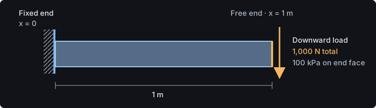
| Model | the steel cantilever of the linear static example: L = 1 m, 100 mm × 100 mm section, E = 200 GPa, ν = 0.3, fixed at x = 0, 1,000 N downward on the end face |
| Tet10 meshes | target sizes 150, 75, 50 and 25 mm |
| Tet4 meshes | target sizes 150 and 50 mm |
| Tolerance on tip deflection | change under 1 % on further refinement |
| Tolerance on stress | change under 2 % on further refinement, for the top-surface von Mises stress at x = 100 mm |
Find
- The coarsest Tet10 mesh that meets both tolerances.
- How the largest element stress behaves under refinement, and why.
- How linear tetrahedra compare with quadratic ones on this bending problem.
Discretization error
Approximation by piecewise polynomials
Each element approximates the displacement with a polynomial of degree : linear for a four-node tetrahedron (Tet4, ) and quadratic for a ten-node tetrahedron (Tet10, ). The finite-element solution is the best such approximation in the energy norm, the norm defined by the stiffness itself:
For a smooth solution and elements of size , the error decreases as a power of the element size:
Strains and stresses converge like the energy norm, one order slower than displacements. Raising the order from 1 to 2 gains a full power of , which is why a coarse Tet10 mesh often beats a fine Tet4 mesh.
Convergence from the stiff side
A displacement-based model can deform only in the shapes its elements allow, so it is stiffer than the real solid. Under an applied load its strain energy approaches the exact value from below, and so does its compliance: the deflection in the direction of the load grows toward the exact value as the mesh is refined. A coarse mesh errs on the unconservative side for deflection.
Bending and element order
In a beam under bending, the strain varies linearly through the depth. A Tet10 element has a linear strain field and represents this exactly within one element. A Tet4 element has constant strain: through the depth it can only approximate the linear variation in steps, and it resists bending with spurious shear strain. A coarse Tet4 mesh of a bending part is therefore far too stiff, an effect known as locking.
Singular points
The estimates above assume a smooth solution. Linear elasticity predicts unbounded stress at a sharp re-entrant corner and where a perfectly rigid support meets a free surface. Near such a point the stress grows like
with the distance from the point. Smaller elements sample closer to the point and report larger values, so the peak never settles. The real part has a fillet radius or a support with some give, and its stress is finite. The singularity belongs to the idealized model, and the fix is to model the detail, not to refine more.
Solution
Outputs to compare
The study gains two outputs, so each run reports the compared quantities directly: the stress at a point a section depth from the wall, and the reaction resultant at the wall.
output top_stress = interpolate(analysis.static.field.node.von_mises_stress, at = [100 mm, 50 mm, 100 mm])
output support_reaction = resultant(analysis.static.field.node.reaction_force, over = geometry.beam.region.fixed_end)
Everything else is the linear static study unchanged, so any change in a result comes from the mesh alone.
Mesh sequence
Only the mesh block changes between runs: its target_size, and for the Tet4 runs its order.
mesh beam on geometry.beam {
    tetrahedra {
        order = quadratic
        target_size = 50 mm
        maximum_deviation = 0.001 m
    }
}
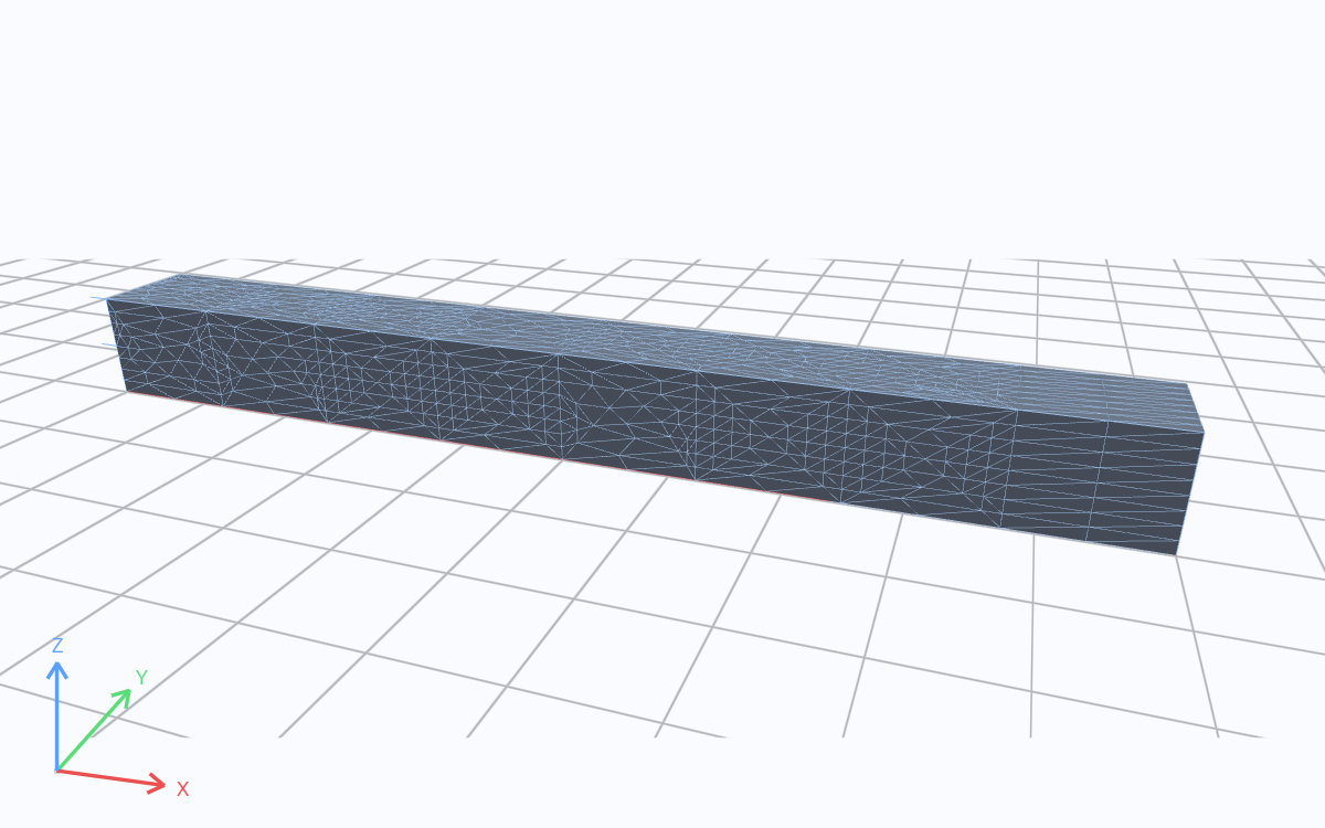
Solver mesh · m. Drag to rotate; scroll to zoom.
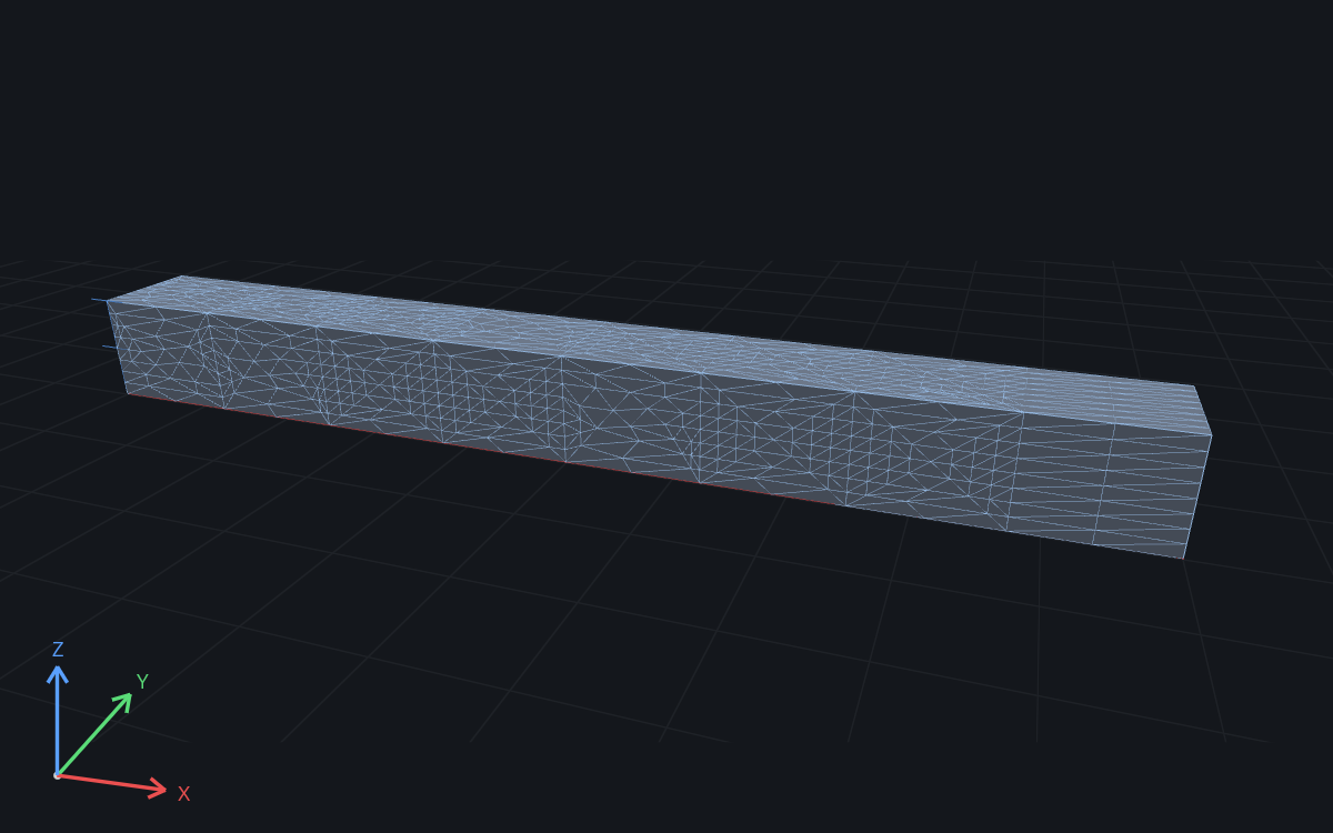
A target size requests an edge length, not an element count. Surface curvature, feature size and quality limits decide the final mesh, so the sequence is compared by node count. On this beam, 75 mm gives almost the same mesh as 150 mm (2,758 nodes against 2,727): a step that barely changes the node count says little about convergence.
Run
Each mesh is one run. With the study saved once per target size, for example as cantilever-50mm.fea:
runmat run cantilever-50mm.fea --jsonThe --json output carries the node count and each output value, so a script can tabulate the sequence. Declaring the target size as a study input and running a sweep does the same in one command.
Import the geometry and choose the mesh
geometry beam {
    file = "./geometry/cantilever.step"
    units = mm
    region body : solid { select name "Beam"; expect exactly_one }
    region fixed_end : face { select name "Fixed end"; expect exactly_one }
    region loaded_end : face { select name "Loaded end"; expect exactly_one }
}

mesh beam on geometry.beam {
    tetrahedra {
        order = quadratic
        target_size = 0.15 m
        maximum_deviation = 0.001 m
    }
}
Choose an elastic material
material steel {
    mass_density = 7850 kg/m^3
    elastic {
        youngs_modulus = 200 GPa
        poisson_ratio = 0.3
    }
}
Fix one end and apply the load
model loaded_beam {
    assign material.steel to geometry.beam.region.body
    constraint fixed_end {
        structural.fixed { target = geometry.beam.region.fixed_end }
    }
    load end_traction {
        traction on geometry.beam.region.loaded_end = [0, 0, -100000] Pa
    }
    load_case service { include load.end_traction }
}
Request the analysis and result fields
study cantilever_static {
    geometry = geometry.beam
    mesh = mesh.beam
    model = model.loaded_beam
    analysis static { structural static {} }
    output displacement = analysis.static.field.node.displacement
    output von_mises = analysis.static.field.element.von_mises_stress
    output tip_deflection = max(magnitude(analysis.static.field.node.displacement), over = geometry.beam.region.loaded_end)
    assessment deflection_limit {
        value = output.tip_deflection
        maximum = 0.5 mm
        evidence = authored_samples
    }
}Includes the study, STEP geometry, and saved results. Run new analyses in RunMat Desktop or the CLI.
View the complete study
// Engineering physics belongs in the importing study.

geometry beam {
    file = "./geometry/cantilever.step"
    units = mm
    region body : solid { select name "Beam"; expect exactly_one }
    region fixed_end : face { select name "Fixed end"; expect exactly_one }
    region loaded_end : face { select name "Loaded end"; expect exactly_one }
}

mesh beam on geometry.beam {
    tetrahedra {
        order = quadratic
        target_size = 0.15 m
        maximum_deviation = 0.001 m
    }
}

material steel {
    mass_density = 7850 kg/m^3
    elastic {
        youngs_modulus = 200 GPa
        poisson_ratio = 0.3
    }
}

model loaded_beam {
    assign material.steel to geometry.beam.region.body
    constraint fixed_end {
        structural.fixed { target = geometry.beam.region.fixed_end }
    }
    load end_traction {
        traction on geometry.beam.region.loaded_end = [0, 0, -100000] Pa
    }
    load_case service { include load.end_traction }
}

study cantilever_static {
    geometry = geometry.beam
    mesh = mesh.beam
    model = model.loaded_beam
    analysis static { structural static {} }
    output displacement = analysis.static.field.node.displacement
    output von_mises = analysis.static.field.element.von_mises_stress
    output tip_deflection = max(magnitude(analysis.static.field.node.displacement), over = geometry.beam.region.loaded_end)
    assessment deflection_limit {
        value = output.tip_deflection
        maximum = 0.5 mm
        evidence = authored_samples
    }
}
Tet10 sequence
| Tet10 target size | Nodes | Tip deflection | Change vs 25 mm | Top-surface stress at x = 100 mm | Change vs 25 mm | Largest element stress |
|---|---|---|---|---|---|---|
| 150 mm | 2,727 | 0.20003 mm | −0.32 % | 5.433 MPa | +0.38 % | 5.39 MPa |
| 75 mm | 2,758 | 0.20030 mm | −0.19 % | 5.422 MPa | +0.18 % | 5.45 MPa |
| 50 mm | 4,679 | 0.20047 mm | −0.10 % | 5.413 MPa | +0.01 % | 5.27 MPa |
| 25 mm | 32,075 | 0.20068 mm | — | 5.412 MPa | — | 5.76 MPa |
Each column behaves as the theory predicts:
- Reaction. It is 1,000 N on every mesh. Equilibrium of the assembled system holds at any resolution, so reactions check the model setup, not the mesh.
- Tip deflection. It grows steadily with refinement, converging from the stiff side. The change from 150 mm to 25 mm is 0.32 %.
- Stress at x = 100 mm. It settles to within 0.4 % across the sequence. The point is a section depth from the wall, where the field is smooth.
- Largest element stress. It moves up and down (5.39, 5.45, 5.27, 5.76 MPa) without settling. It sits in an element on the fixed edge, the singular point of this model.
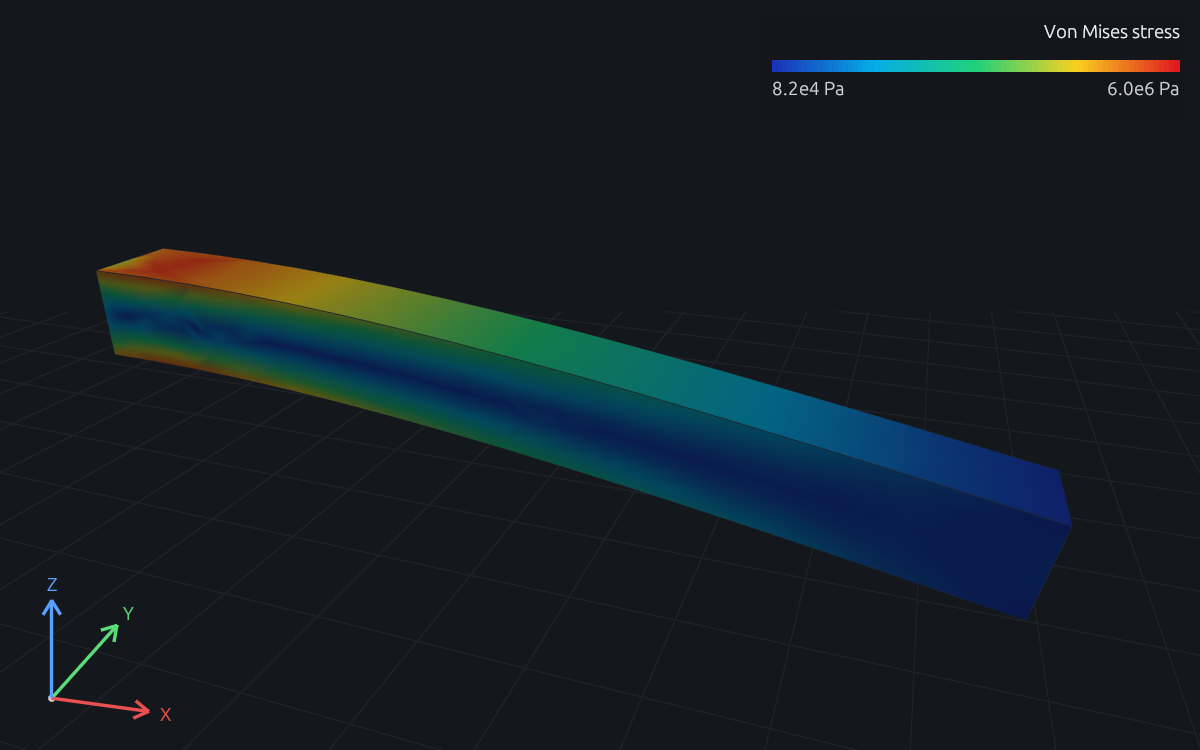
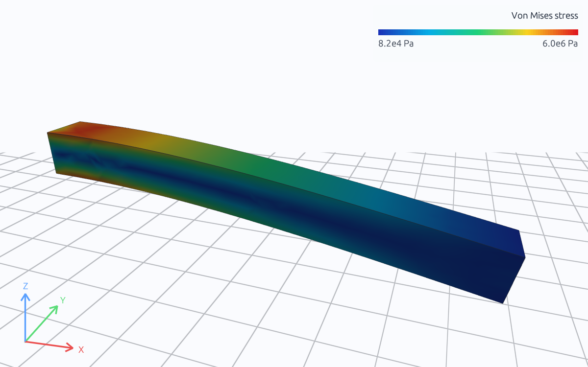
Von Mises stress · Pa · 8.25e+4 to 6.02e+6. Drag to rotate; scroll to zoom.
Tet4 runs
| Tet4 target size | Nodes | Tip deflection | Short of the Tet10 25 mm value |
|---|---|---|---|
| 150 mm | 431 | 0.1007 mm | 50 % |
| 50 mm | 729 | 0.1625 mm | 19 % |
The coarse Tet4 mesh deflects half as much as it should: the locking described above. Refining helps slowly, while the coarsest Tet10 mesh is already within 0.4 % of the finest.
Answers
- The 150 mm Tet10 mesh meets both tolerances: the tip deflection changes by 0.32 % and the stress at x = 100 mm by 0.38 % on refinement to 25 mm, inside the 1 % and 2 % limits.
- The largest element stress does not converge and never will, because it sits at the singular edge where the rigid support meets the free surface. It is not a design value.
- Linear tetrahedra lock in bending: at 150 mm they recover half the deflection, and at 50 mm they are still 19 % short. For bending-dominated parts, changing the element order does more than refining a linear mesh.
Discussion
Choosing the quantity. A convergence study answers a question about one quantity, so it starts with the quantity the decision rests on. Displacements, reactions and stresses away from singular points converge; peak stresses at idealized corners and supports do not. Checking the convergence of a singular peak only produces a growing number.
Choosing the tolerance. A tolerance well inside the design margin is enough. In the linear static example the deflection uses 40 % of its limit and the stress under 4 % of its allowable; a 1 to 2 % mesh error cannot change either verdict.
Spending nodes where they matter. Refining everywhere from 50 mm to 25 mm multiplied the node count by seven for a 0.1 % change. When one region controls the answer, such as a fillet or a hole, a local sizing control refines only there.
When the peak matters. If the stress at the joint is the design question, the model must contain the joint: the weld fillet, the bolt or the support's compliance. The singularity then disappears, and the peak becomes a quantity that converges like any other.
Try a change
Problem 1.1. Add a local sizing control on the fixed face and rerun the 150 mm mesh. Predict which outputs change. Answer: the tip deflection and the stress at x = 100 mm should not change appreciably; the largest element stress at the edge will.
Problem 1.2. Run Tet4 at 25 mm and compare its tip deflection and node count with the Tet10 runs. Estimate how many Tet4 nodes the 0.32 % accuracy of the coarsest Tet10 mesh would need.
Problem 1.3. Move the stress sample to x = 20 mm and repeat the sequence. Explain why the sampled stress changes more between meshes close to the singular edge.
Next
- Linear static analysis: the model this example refines.
- Meshing: element orders, sizes and local refinement.
- Structural validation: this sequence compared with beam theory.