
Make fabrication outputs
This guide sends the pressure sensor board from Lay out a board out for manufacture: a set of files for the board house that makes the bare board, and a set for the assembly house that places the parts. The Desktop's Fabrication outputs panel, design.export and runmat-design export --format fabrication make the same files from the same settings.
1. Choose a preset
Open Fabrication outputs from the board tab. A preset picks the outputs:
| Preset | Outputs | For |
|---|---|---|
| Fab house | Gerber X2 per layer with the job file, Excellon drill files and the drill map, the fabrication drawing, the IPC-D-356A test netlist | the board house |
| Assembly | pick-and-place, the bill of materials, the assembly drawing of each side | the assembly house |
| Full | everything above, with IPC-2581 and ODB++ | a house that takes a single-file format |
| Custom | the outputs you switch on | anything else |
2. Check the layer table
The layer table lists the board top to bottom as the stackup builds it: paste, legend, mask, each copper layer with its weight, the dielectrics between them, then the bottom's layers, the courtyards and the outline. Each row shows its material, its thickness and the Gerber file it makes. Courtyards are off by default; switch a row off to leave its file out. Selecting a Gerber row previews that layer alone as it will be made, drawn from its Gerber image, with the mask shown as its openings.
3. Set the formats
Each output has its own settings in the panel:
- Gerber: millimeters or inches, and the number of decimals.
- Pick and place: both sides in one file, a file per side, or one side only; millimeters or inches; whether through-hole parts are listed.
- BOM: the columns (designators, quantity, value, package, MPN, manufacturer), and one line per value or one line per designator.
- Variants: which variants get assembly files. A part a variant leaves unfitted is left out of that variant's pick-and-place file and BOM.
- Revision and folder: the revision goes into the Gerber and job files and the fabrication drawing, and the default folder is
fab/<board>-<revision>. Zip packs the set into one archive.
The board keeps the settings you generate with, so the next export from the Desktop, the agent or the command line makes the same files. The circuit and the board's fabrication line:
runmat 0.7
std 1

circuit baro {
    root = main
    net_class power = { track_width = "0.40 mm", clearance = "0.20 mm" }

    sheet main {
        component J1 = { part = "CONN-SH-4P" }
        component U1 = { part = "LDO-3V3-SOT23" }
        component C1 = { part = "C0805-1U" }
        component C2 = { part = "C0402-1U" }
        component R1 = { part = "R0402-4K7" }
        component R2 = { part = "R0402-4K7" }
        component R3 = { part = "R0402-1K" }
        component D1 = { part = "LED0603-G" }
        component U2 = { part = "BARO-LGA8" }
        component C3 = { part = "C0402-1U" }
        net GND = { class = power, global = true, power_flag = true }
        net VIN = { class = power, power_flag = true }
        net "+3V3" = { class = power, global = true }
        connect = [net.VIN, "J1.1", U1.VIN, U1.EN, "C1.1"]
        connect = [net.SDA, "J1.2", "R1.2", U2.SDA]
        connect = [net.SCL, "J1.3", "R2.2", U2.SCL]
        connect = [net.GND, "J1.4", U1.GND, "C1.2", "C2.2", D1.K, U2.GND, U2.SDO, "C3.2"]
        connect = ["net.+3V3", U1.VOUT, "C2.1", "R1.1", "R2.1", "R3.1", U2.VDD, U2.VDDIO, U2.CSB, "C3.1"]
        connect = [net.LED, "R3.2", D1.A]
        no_erc = [U1.NC]
    }
}
runmat 0.7
std 1
use circuit baro
layout baro {
outline = [[0, 0], [20, 0], [20, 15], [0, 15]]
limits = { clearance = 0.15, track = 0.15, via_diameter = 0.45, drill = 0.2, annular = 0.1, hole_to_hole = 0.25, copper_to_edge = 0.3, silk_to_pad = 0.1, microvia_drill = 0.1 }
fabrication = { preset = fab_house, outputs = [gerber, drill, drill_map, drawing, ipc356], folder = "fab/baro-A", zip = true, gerber = { units = mm, decimals = 6 }, revision = "A" }
}4. Run the pre-flight
Generate runs the pre-flight first: DRC findings, ERC findings, unrouted connections and schematic changes the board hasn't taken, each with its count. With any count above zero the panel says how many issues it found and that a board house may reject the files, and offers Export anyway or Back. Fix the issues, or export anyway for a prototype you know about.
5. The results
The results list every file written, with its format, the layer or role it holds and its size, and each opens or shows in its folder. A Gerber file in the list previews its layer.
Here the pre-flight is clean, so Generate writes the fab-house package straight away and lists its files under the board:
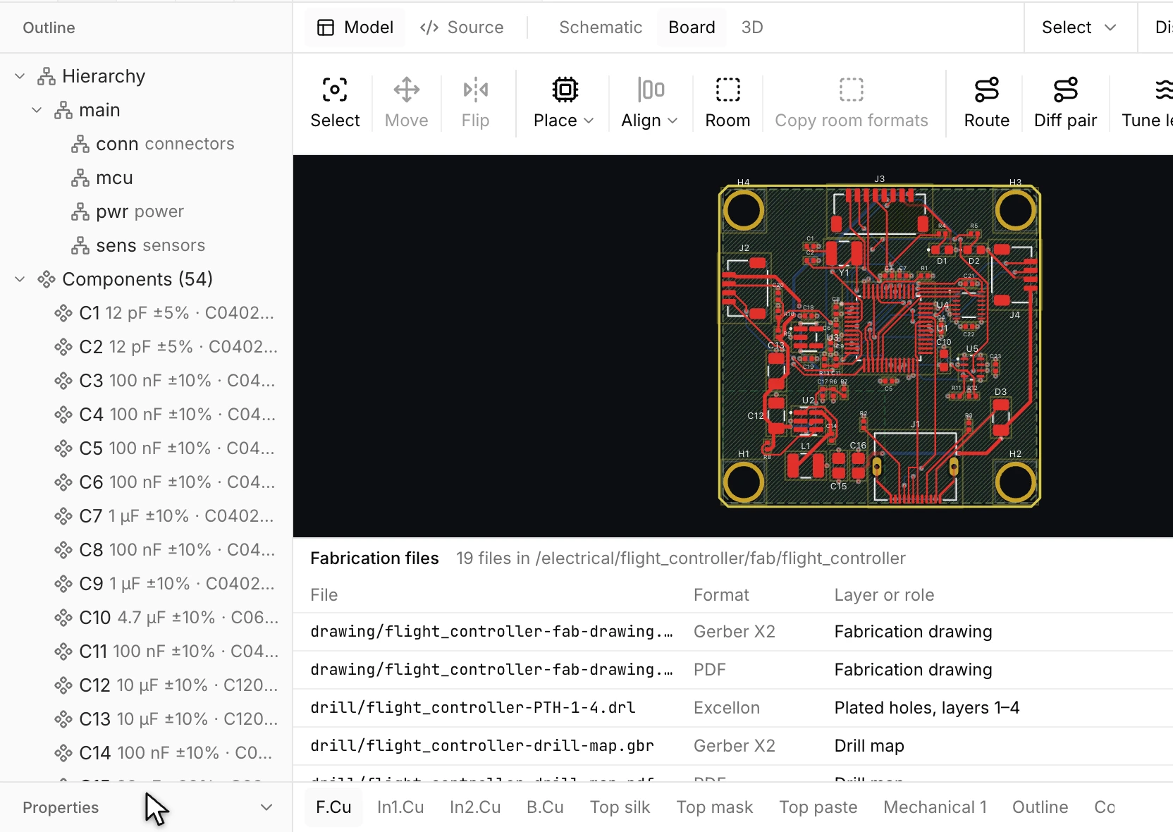
| Folder | Holds |
|---|---|
gerber/ | Gerber X2 per layer and the .gbrjob job file with the stackup |
drill/ | Excellon files per drill span and for non-plated holes, and the drill map as Gerber and PDF |
drawing/ | the fabrication drawing as Gerber and PDF: drill table, board size, layer and stackup table, notes |
assembly/ | the BOM and the pick-and-place file of each variant, and the assembly drawing of each side (outlines and designators) as Gerber and PDF |
ipc2581/, odb/ | IPC-2581C and ODB++ |
netlist/ | IPC-D-356A for bare-board electrical test |
6. From the command line
The command reads the board's saved settings, and each flag overrides one:
runmat-design export baro.circuit.layout --format fabrication
runmat-design export baro.circuit.layout --format fabrication --preset assembly --variant "" --out fab/assembly
runmat-design export baro.circuit.layout --format fabrication --gerber-units inch --revision B --remember
--remember saves the flags' settings into the board. See Fabrication outputs and netlists for every option.
Next
- Fabrication outputs and netlists lists every output, setting and flag.
- Import brings boards in from other tools.