
Model a part
This guide builds a motor mounting plate from an empty file to a part an assembly can place, a drawing can dimension and a study can load. Each step adds a few lines to motor_plate.part; the Desktop draws the same steps on the canvas and writes the same text, so you can work in either view.
The finished plate is 60 mm square and 5 mm thick, with a center bore for the motor shaft, four mounting holes on a bolt circle and rounded corners.
1. Start the file
Run New Part in the Desktop, or create motor_plate.part in the project folder. Every design file starts with the language version and the standard library version, then one part block named after the file:
runmat 0.7
std 1

part empty_plate {
}
2. Sketch the profile and make it solid
A sketch lies on a plane and holds lines, arcs and circles. Constraints fix its shape: here the square's corner is fixed at the origin, its sides are horizontal and vertical, and its two sides are equal. extrude turns the closed profile into a solid.
runmat 0.7
std 1

part plate_sketch {
    sketch outline on origin.xy {
        bottom = line(start = [0 mm, 0 mm], end = [60 mm, 0 mm])
        right = line(start = bottom.end, end = [60 mm, 60 mm])
        top = line(start = right.end, end = [0 mm, 60 mm])
        left = line(start = top.end, end = bottom.start)
        constrain fix(bottom.start)
        constrain horizontal(bottom)
        constrain vertical(right)
        constrain equal(bottom, right)
        constrain length(bottom) = 60 mm
    }
    feature body = extrude(profile = sketch.outline, distance = 5 mm)
    output plate_sketch = { body = feature.body.body }
}
The sketch's status shows in the Outline: fully constrained, or the number of free directions left. An over-constrained sketch is an error on the constraint that conflicts. See Sketches and constraints.
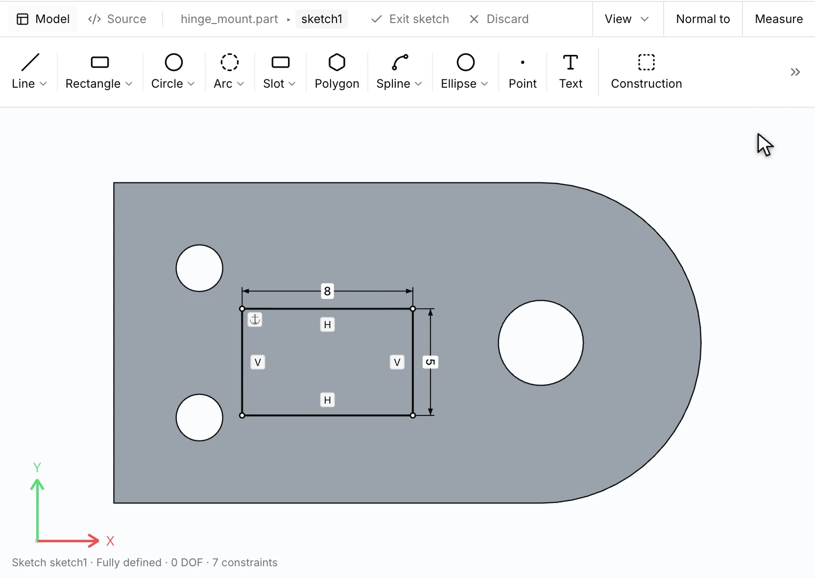
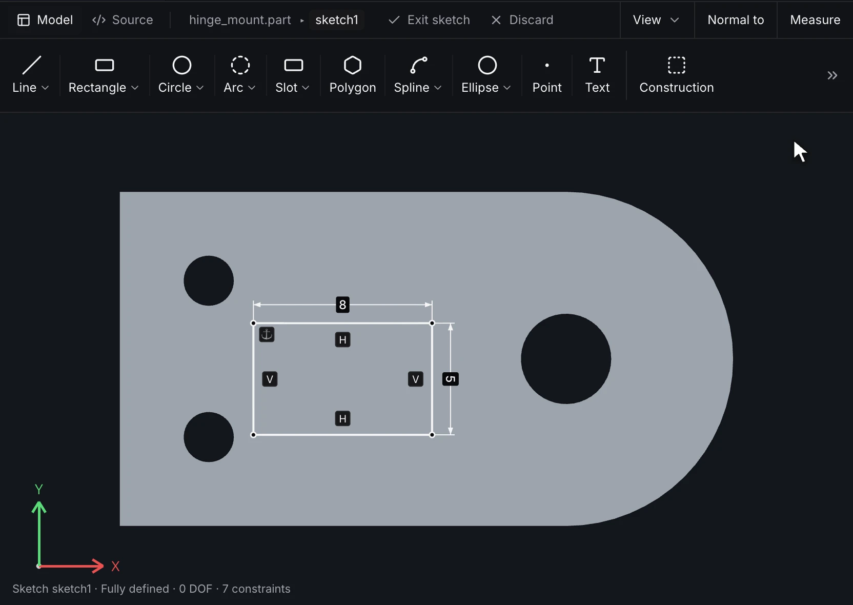
In the Desktop, Sketch on a face opens the sketch on that face. Rectangle draws a profile that already carries its horizontal and vertical relations, and Smart dimension sets each side. Fix holds a corner in place. The status line under the view counts the free directions that are left, down to 0 when the sketch is fully defined:
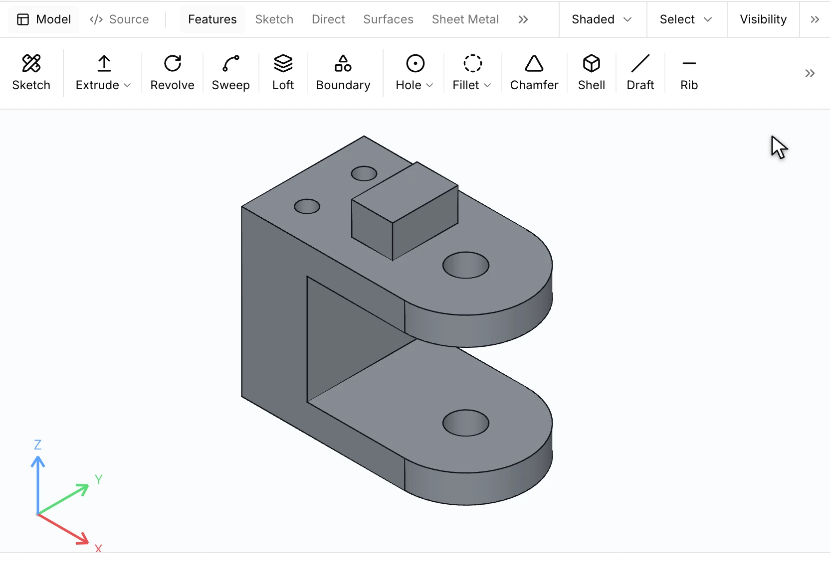
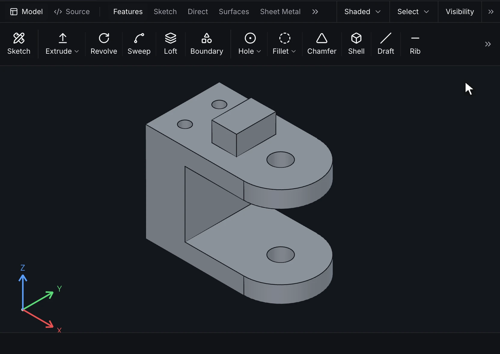
Extrude takes the sketch as its profile and previews the solid. Type the depth in the box on the model or in the form, then confirm:
3. Drive the sizes from inputs
Inputs turn literal sizes into parameters that assemblies, configurations and runs can set. Each input has a quantity kind and a default, and an input's bounds stop a value the design can't take:
input size : length = { default = 60 mm, minimum = 40 mm, maximum = 120 mm }
input thickness : length = 5 mm
Replace each literal with input.size or input.thickness. The Properties panel then lists the inputs with their units, and editing one writes the new default into the file.
4. Add holes and rounds
hole drills one hole at each key of at, starting on a planar face. The keys name each hole's faces, so the bore's wall is feature.bore.face.wall(c). fillet rounds the four vertical corner edges, each named as the edge between two side faces of the extrude.
runmat 0.7
std 1

part motor_plate {
    input size : length = { default = 60 mm, minimum = 40 mm, maximum = 120 mm }
    input thickness : length = 5 mm
    input inset : length = 14 mm

    sketch outline on origin.xy {
        bottom = line(start = [0 mm, 0 mm], end = [input.size, 0 mm])
        right = line(start = bottom.end, end = [input.size, input.size])
        top = line(start = right.end, end = [0 mm, input.size])
        left = line(start = top.end, end = bottom.start)
        constrain fix(bottom.start)
        constrain horizontal(bottom)
        constrain vertical(right)
        constrain equal(bottom, right)
        constrain length(bottom) = input.size
    }
    feature body = extrude(profile = sketch.outline, distance = input.thickness)

    feature bore = hole(face = feature.body.face.end, at = { c = point(input.size / 2, input.size / 2, input.thickness) }, diameter = 22 mm, through_all)
    feature mount = hole(
        face = feature.body.face.end,
        at = { a = point(input.inset, input.inset, input.thickness), b = point(input.size - input.inset, input.inset, input.thickness), c = point(input.size - input.inset, input.size - input.inset, input.thickness), d = point(input.inset, input.size - input.inset, input.thickness) },
        through_all,
        spec = { standard = iso, size = M3 }
    )
    feature corners = fillet(
        edges = [
            edges_between(feature.body.face.side(outline.bottom), feature.body.face.side(outline.right)),
            edges_between(feature.body.face.side(outline.right), feature.body.face.side(outline.top)),
            edges_between(feature.body.face.side(outline.top), feature.body.face.side(outline.left)),
            edges_between(feature.body.face.side(outline.left), feature.body.face.side(outline.bottom))
        ],
        radius = 4 mm
    )

    output motor_plate = { body = feature.body.body, part_number = "MP-060", material = "material.aluminum_6061" }

    region seat : face = { select = [feature.body.face.start], expect = exactly_one, label = "Motor seat" }
    region bolts : face = { select = [feature.mount.face.wall(a), feature.mount.face.wall(b), feature.mount.face.wall(c), feature.mount.face.wall(d)], expect = at_least_one, label = "Mounting bores" }
    publish seat = region(region = seat)
    publish thickness = value(input = thickness)
}
spec = { standard = iso, size = M3 } sets the clearance diameter from the standard, and a drawing's hole callout reads it. See Features for every operation.
5. Name what other files use
Three statements at the end make the part usable by other files:
output motor_platedeclares the delivered part: its body, part number and material. The material sets the density for mass properties and the material a study assigns.region seatandregion boltsname face sets and check them:expect = exactly_onemakes the check fail if an edit splits or removes the seat face. A study loadsboltsby name, and the name survives every edit that keeps those faces.publishmakes the seat region and the thickness readable by assemblies and other parts.
See Outputs, regions and published values.
6. Check and weigh it
The source view marks each problem at its line as you type. A feature that fails names its root cause, and the features after it that fail because of it are listed under that root, each with a repair such as Re-pick or Suppress. Run the same check from the agent or a script with design.check.
Evaluate's Mass properties command weighs the plate from its material's density: mass, center of gravity and inertia about it. See Evaluate.
Next
- Build an assembly places this plate and mates a part to it.
- Make a drawing dimensions it from its features.
- Product families and configurations adds sizes of the same plate.