
Sheet metal
This guide designs a vent cover bent from 1.5 mm sheet: a 120 × 80 mm top with three flanges, relief cuts at the corners, two louvers, and its flat pattern drawn for the laser cutter and the press brake.
1. The base flange and its rules
A sheet-metal part starts with a base flange. A closed sketch makes a flat plate; an open chain of lines makes a bent profile, with a bend at each corner. The flange carries the rules every later bend uses:
thickness: the sheet thickness;bend_radius: the inside bend radius;rule: how a bend develops into the flat.k_factor(k = 0.44)puts the neutral axis at 0.44 of the thickness from the inside face.
The bend allowance of a bend through angle with inside radius , thickness and K-factor is
so a 90° bend with = 2 mm, = 1.5 mm and = 0.44 develops 4.18 mm of flat.
2. Flanges, reliefs and formed features
runmat 0.7
std 1

part vent_cover {
    sketch s_plate on origin.xy {
        e1 = line(start = [0 mm, 0 mm], end = [120 mm, 0 mm])
        e2 = line(start = [120 mm, 0 mm], end = [120 mm, 80 mm])
        e3 = line(start = [120 mm, 80 mm], end = [0 mm, 80 mm])
        e4 = line(start = [0 mm, 80 mm], end = [0 mm, 0 mm])
    }
    feature base = sheet_metal.base_flange(
        profile = sketch.s_plate,
        rules = { thickness = 1.5 mm, bend_radius = 2 mm, rule = k_factor(k = 0.44) }
    )
    feature front = sheet_metal.edge_flange(
        edges = [edges_between(feature.base.face.sheet(plate, ordinal = 1), feature.base.face.sheet_edge(e1))],
        length = 20 mm,
        angle = 90 deg,
        length_reference = tangent
    )
    feature side = sheet_metal.edge_flange(
        edges = [edges_between(feature.base.face.sheet(plate, ordinal = 1), feature.base.face.sheet_edge(e2))],
        length = 20 mm,
        angle = 90 deg,
        length_reference = tangent
    )
    feature back = sheet_metal.edge_flange(
        edges = [edges_between(feature.base.face.sheet(plate, ordinal = 1), feature.base.face.sheet_edge(e3))],
        length = 20 mm,
        angle = 90 deg,
        length_reference = tangent
    )
    feature relief = sheet_metal.corner_relief(
        corners = [feature.base.face.sheet(plate, ordinal = 1)],
        relief = rectangular(size = 3 mm)
    )
    feature louver1 = sheet_metal.form_tool(
        tool = louver(length = 50 mm, width = 6 mm, height = 4 mm),
        face = feature.base.face.sheet(plate, ordinal = 1),
        at = point(45 mm, 40 mm, 1.5 mm),
        rotation = 90 deg
    )
    feature louver2 = sheet_metal.form_tool(
        tool = louver(length = 50 mm, width = 6 mm, height = 4 mm),
        face = feature.base.face.sheet(plate, ordinal = 1),
        at = point(75 mm, 40 mm, 1.5 mm),
        rotation = 90 deg
    )
    feature flat = sheet_metal.flat_pattern(fixed_face = feature.base.face.sheet(plate, ordinal = 1))
    output vent_cover = { body = feature.base.body, part_number = "VC-120", material = "material.steel_dc01" }
}- Faces of a sheet are named by the sketch entity they come from:
feature.base.face.sheet(plate, ordinal = 1)is the plate's top face (ordinal 0 is the bottom), andsheet_edge(e2)is the side face along sketch linee2. An edge flange names its edge as the edge between those two faces. length_reference = tangentmeasures the flange length from the tangent point of the bend.outerandinnermeasure from the outside or inside face.corner_reliefcuts a relief where two flanges meet, so the corner folds without tearing.form_toolpresses a louver or a dimple into a face at a point.
Other operations add hems, jogs, miter flanges, sketched and lofted bends, tabs and slots, and closed or broken corners. See Features.
convert_to_sheet_metal turns a thin solid, such as a shelled box, into sheet metal:
feature sheet = sheet_metal.convert_to_sheet_metal(
    fixed_face = feature.body.face.start,
    bend_edges = [],
    rules = { thickness = 1.5 mm, bend_radius = 1 mm, rule = k_factor(k = 0.44) }
)- The fixed face is a flat face with straight edges and a face one sheet thickness behind it. Its outline becomes the plate.
- At each bend edge of the fixed face, the wall standing on that edge becomes a bend of the sheet's radius and a flat. The face the wall stood on stays where it was: pick the outer floor and the outer wall faces stay put; pick the inner floor and the inner faces stay put. With
bend_edges = [], every edge with a wall bends. Walls on edges left out of a non-empty list are removed. - Where two bent walls meet at a corner, each stops short of the corner by the other's bend setback, and the plate's corner inside both setbacks is cut away. The square relief appears in the folded part and in its flat pattern. For 90° walls the setback is the bend radius when the inner floor is fixed, and the bend radius plus the thickness when the outer floor is fixed.
- The converted plate unfolds, folds and has a flat pattern like a plate with edge flanges.
3. The flat pattern
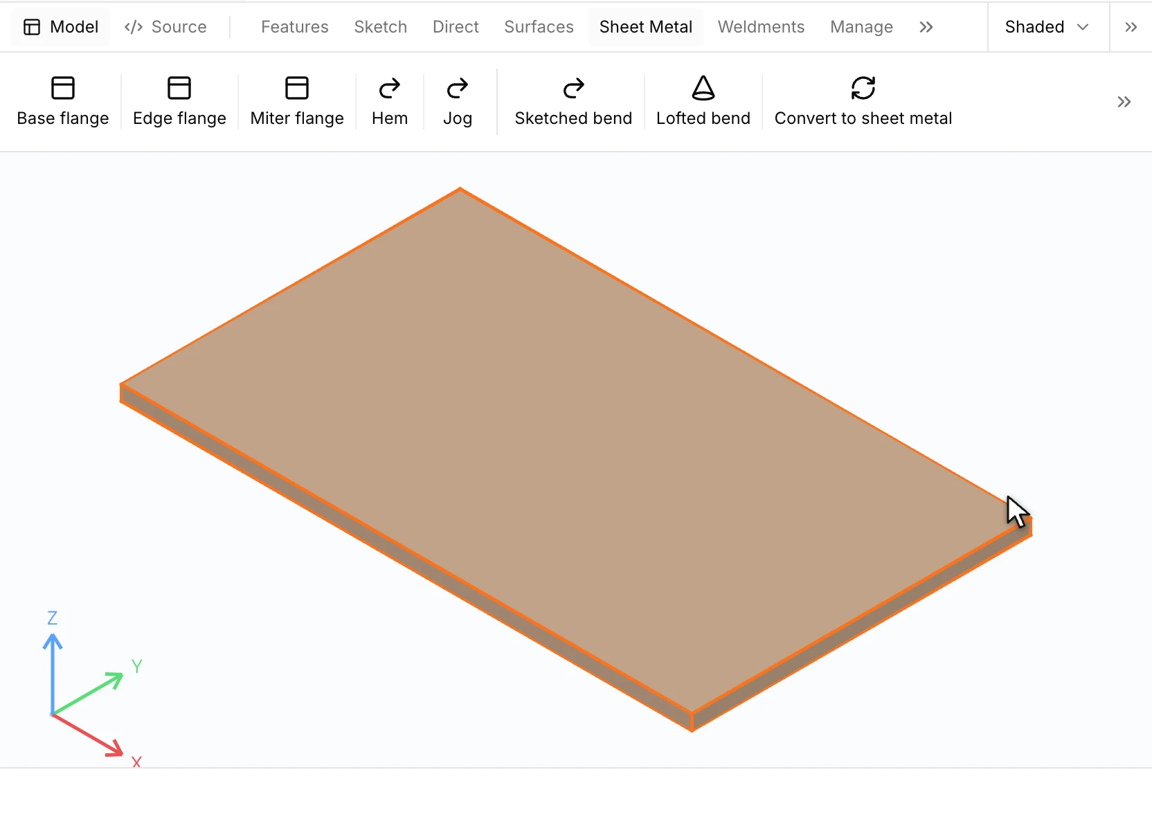
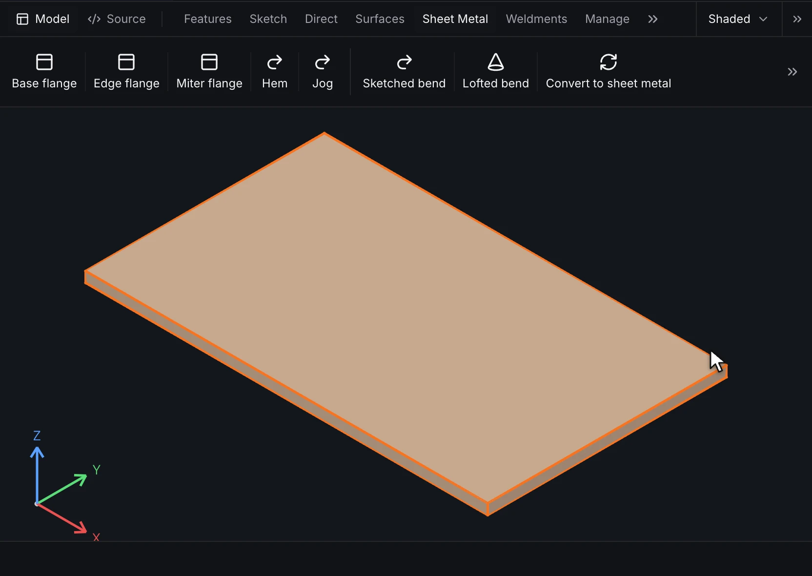
flat_pattern(fixed_face = …) unfolds the part with the chosen face held still. The flat body sits beside the folded one and is kept out of the folded display. Each bend's development comes from the base flange's rule, so a change to the thickness or the K-factor changes the flat.
4. Draw it for the shop
A flat_pattern view draws the developed outline with its bend lines and a note on each bend (direction, angle, radius and allowance). A bend table lists the bends in the order of their lines.
runmat 0.7
std 1

drawing vent_cover_flat {
    format a3 = {
        size = { size = iso, name = A3 },
        title_block = [
            { label = "Title", source = { source = literal, text = "Vent cover, flat pattern" } },
            { label = "Part number", source = { source = property, name = part_number } },
            { label = "Scale", source = { source = scale } }
        ]
    }
    sheet "1" = { format = a3, scale = [1, 1], projection = third_angle }
    view flat = flat_pattern(feature = flat, sheet = "1", model = { part = vent_cover }, at = [200, 170], display = visible_lines)
    table bends = bend(view = flat, sheet = "1", at = [20, 120])
}
Export the flat pattern as DXF for the cutter:
runmat-design export vent_cover.part --format dxf --out flat
runmat-design export vent_cover_flat.drawing --format pdf --out drawings
5. Check it for manufacture
Evaluate's design-for-manufacture check runs the sheet-metal rule pack, which checks bend radius over thickness among its rules, and reports each failure on its feature. See Design for manufacture.
Next
- Make a drawing covers sheets, views and annotations in full.
- Product families and configurations makes thicker or longer versions of the cover.